ORC for transporting waste heat from a heat source into mechanical energy and cooling system making use of such an ORC

Active Publication Date: 2020-04-07
ATLAS COPCO AIRPOWER NV
View PDF27 Cites 8 Cited by
  • Summary
  • Abstract
  • Description
  • Claims
  • Application Information

AI Technical Summary

Benefits of technology

[0023]An advantage of an ORC according to the invention is that the evaporator is filled with boiling liquid working fluid, thereby maximizing the contact surface between the liquid working fluid and the heat source and thereby maximizing the heat transfer with the heat source and thereby maximizing the amount of heat recovered from the heat source to be transformed into mechanic

Problems solved by technology

A disadvantage of the existing ORC's is that the size of the evaporator has to be relatively large in order to have a sufficient heat transfer contact between the working fluid in the evaporator and the heat source, especially with a low temperature heat source of for example 90° C. or even 60° C., the contact surface between the liquid fraction of the working fluid to be evaporated in the evaporator being only a small fraction of the total contact surface of the evaporator since the evaporator only contains liquid at the bottom and vapors of the working fluid on top of it.
Another disadvantage is that in case of a failure of the liquid pump or expander, the circul

Method used


Image

  • ORC for transporting waste heat from a heat source into mechanical energy and cooling system making use of such an ORC
  • ORC for transporting waste heat from a heat source into mechanical energy and cooling system making use of such an ORC

Examples


Embodiment Construction

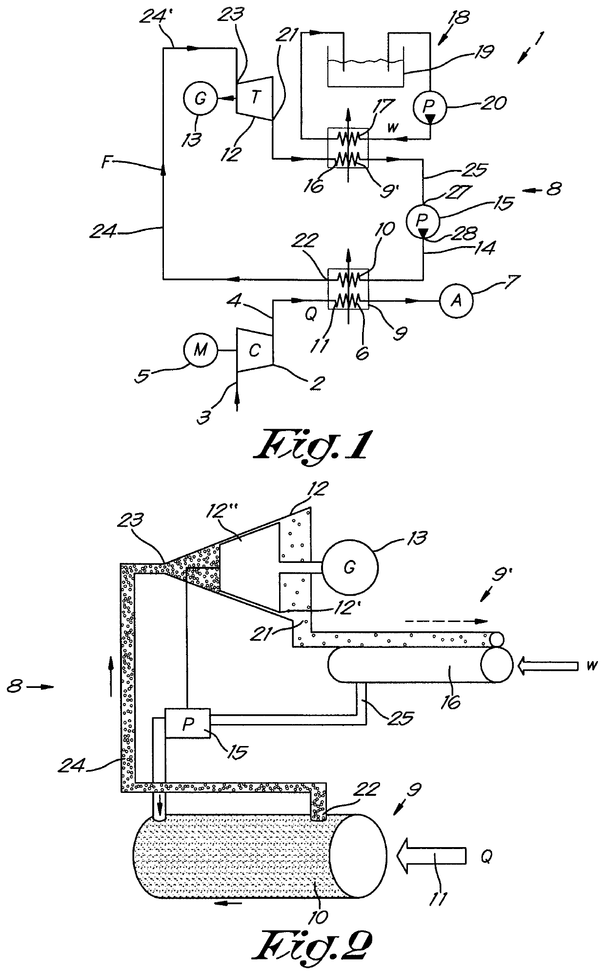
[0032]The cooling system 1 represented in FIG. 1 is a cooling system for cooling for example the compressed gas produced by a compressor installation comprising a compressor element 2 with an inlet 3 and an outlet 4, said compressor element 2 being connected to a motor 5 for driving the compressor element 2 for compressing a gas flow Q. Further, the cooling system 1 comprises a cooler 6, which is provided downstream of said compressor element 2, for cooling the compressed gas before it is supplied to a net 7 of consumers of compressed gas.

[0033]The cooling installation 1 comprises an ORC 8 according to the invention wherein the above-mentioned cooler 6 is integrated in a heat exchanger 9 which further integrates an evaporator 10 of the ORC 8 for recovering the waste heat of the compressed gas used as a heat source 11 being configured to transform said heat into useful mechanical energy by means of an expander 12 of the ORC 8, for example a turbine driving an electrical generator 13 ...


PUM


Abstract

An Organic Rankine Cycle (ORC) device and method for transforming heat from a heat source into mechanical energy. The ORC includes a closed circuit containing a two phase working fluid. The circuit comprises a liquid pump for circulating the working fluid consecutively through an evaporator which is configured to be placed in thermal contact with the heat source; through an expander for transforming the thermal energy of the working fluid into mechanical energy; and through a condenser which is in thermal contact with a cooling element. The expander is situated above the evaporator. The fluid outlet of the evaporator is connected to the fluid inlet of the expander by a raiser column which is filled with a mixture of liquid working fluid and of gaseous bubbles of the working fluid, which mixture is supplied to the expander.

Description

[0001]The present invention relates to an ORC for transforming waste heat from a heat source into mechanical energy and to a cooling system making use of such an ORC for cooling a source of waste heat.BACKGROUND OF THE INVENTION[0002]Power cycles for WTP (Waste heat to Power) are well described, such as ORC, Kalina, Trilateral Flash etc.[0003]Such power cycles are designed to recover waste heat from the heat source and to transform said energy into useful mechanical energy that can be used for instance for driving a generator for generating electrical power.[0004]The use of an ORC (Organic Rankine Cycle) is in particular known to recover waste energy of heat sources with relatively low temperature like the heat of compressed gas produced by a compressor installation, or comprised in exhaust gasses, flue gasses, steam, hot water or the like.[0005]Such known ORC's comprise a closed loop circuit containing a two-phase working fluid, the circuit further comprising a liquid pump for circ...

Claims


Application Information

Patent Timeline
IPC IPC(8): F01K11/00F01K25/04F01K25/08F01K9/00F01K25/14F01K21/00
CPCF01K11/00F01K25/04F01K21/005F01K25/08F01K25/14F01K9/003
Inventor OHMAN, HENRIK
Owner ATLAS COPCO AIRPOWER NV
Why Eureka
Try Eureka