Method for estimating the flow rate of recirculated exhaust gas passing through a valve

Active Publication Date: 2020-04-14
CONTINENTAL AUTOMOTIVE FRANCE
View PDF14 Cites 4 Cited by
  • Summary
  • Abstract
  • Description
  • Claims
  • Application Information

AI Technical Summary

Benefits of technology

The objective of this patent is to minimize the cost of the exhaust gas recirculation system and improve the accuracy of calculating the amount of recirculated gas flows.

Problems solved by technology

Thus, the presence of exhaust gases, which are chemically inert, and have a high heat capacity, reduces the temperature of the exhaust gas.
This solution is therefore relatively expensive, and the integration of three sensors near the valve can be tricky.
In addition, when the upstream and downstream pressures of the valve are close, the flow curve has a very steep slope, and therefore offers low accuracy.
These conditions are encountered in particular when the torque delivered by the engine is low.
Indeed, the counterpressure in the exhaust circuit is low under these conditions.

Method used


Image

  • Method for estimating the flow rate of recirculated exhaust gas passing through a valve
  • Method for estimating the flow rate of recirculated exhaust gas passing through a valve

Examples


Embodiment Construction

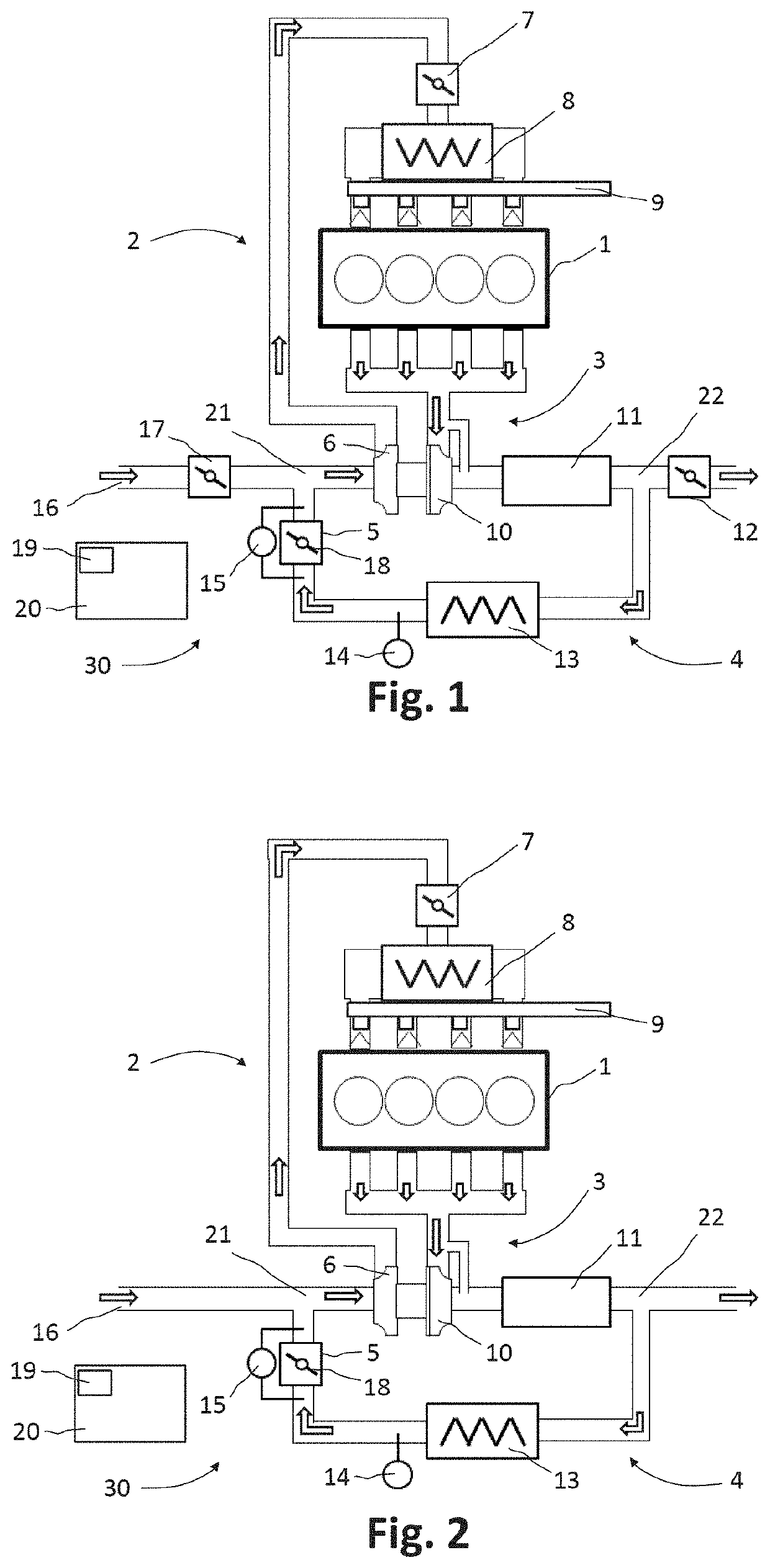
[0071]FIG. 1 shows a combustion engine 1 equipped with its various components.

[0072]Engine 1 includes an intake circuit 2 of combustion gas, an exhaust circuit 3 of burnt gases and a recirculation circuit 4 of the exhaust gas.

[0073]The combustion air supplying engine 1 is admitted through inlet 16 of the intake circuit 2, and is then compressed by a forced induction device, including a compressor 6 driven by a turbine 10 secured to the same axis as the compressor 6. The flow of gas leaving the compressor 6 is cooled in the heat exchanger 8. The flow rate of this flow is adjusted by a metering valve, called a throttle body 7, and supplies the engine 1 with combustion gas. The intake distributor distributes the flow through the throttle body 7 between the different cylinders of the engine 1.

[0074]The fuel is injected into the engine 1 by an injection system 9 and burned in the combustion chambers, thus allowing the engine 1 to supply mechanical energy.

[0075]Engine 1 is a spark ignitio...


PUM


Abstract

Disclosed is a method for estimating the flow rate QEGR of exhaust gases recirculated through an exhaust gas recirculation valve connecting an exhaust circuit and an intake circuit of a combustion engine, the method including the steps: —of determining a difference in pressure ΔP between the upstream and downstream sides of the valve, determining a density ρEGR of the recirculated exhaust gases passing through the valve, determining a corrected effective area Seff_cor of the valve, estimating the flow rate QEGR of the recirculated exhaust gases from these three parameters.

Description

[0001]The present invention relates to a method for estimating the flow of exhaust gas recirculated through a recirculation valve, for a heat engine, especially for a motor vehicle.BACKGROUND OF THE INVENTION[0002]The principle of recirculating a portion of the exhaust gas of an internal combustion engine, for example in a motor vehicle, is known. Mixing exhaust gases with fresh intake air changes the course of combustion of the fuel mixture. Thus, the presence of exhaust gases, which are chemically inert, and have a high heat capacity, reduces the temperature of the exhaust gas. For a spark ignition engine, the self-ignition tendency of the mixture is also reduced, which decreases the engine's knocking tendency. In addition, recirculation of exhaust gases makes it possible to reduce losses from pumping. Thus, the use of exhaust gas recirculation makes it possible to reduce specific fuel consumption, which makes it a very interesting technology. To optimize the operation of the engi...

Claims


Application Information

Patent Timeline
IPC IPC(8): F02D41/00F02M26/06F02M26/47
CPCF02D41/0065F02M26/47F02D41/0072F02M26/06F02D2041/0067Y02T10/47F02D2200/0402Y02T10/40
Inventor LUTZ, PHILIPPEDAVID, FLORENTSURBLED, KÉVIN
Owner CONTINENTAL AUTOMOTIVE FRANCE
Why Eureka
Try Eureka