Cryogenic heating system

Active Publication Date: 2020-04-21
NAT TECH & ENG SOLUTIONS OF SANDIA LLC
View PDF5 Cites 1 Cited by
  • Summary
  • Abstract
  • Description
  • Claims
  • Application Information

AI Technical Summary

Benefits of technology

[0005]Accordingly, the present invention relates to a system that employs an inert fluid (e.g., an inert gas, a cryogenic fluid capable of being converted into an inert gas, etc.) to provide non-contact heating and cooling of a test sample. The system can include the use of multiples stages of heaters to control the temperature of the inert

Problems solved by technology

In situ heating and cooling of samples c

Method used


Image

  • Cryogenic heating system
  • Cryogenic heating system
  • Cryogenic heating system

Examples


example

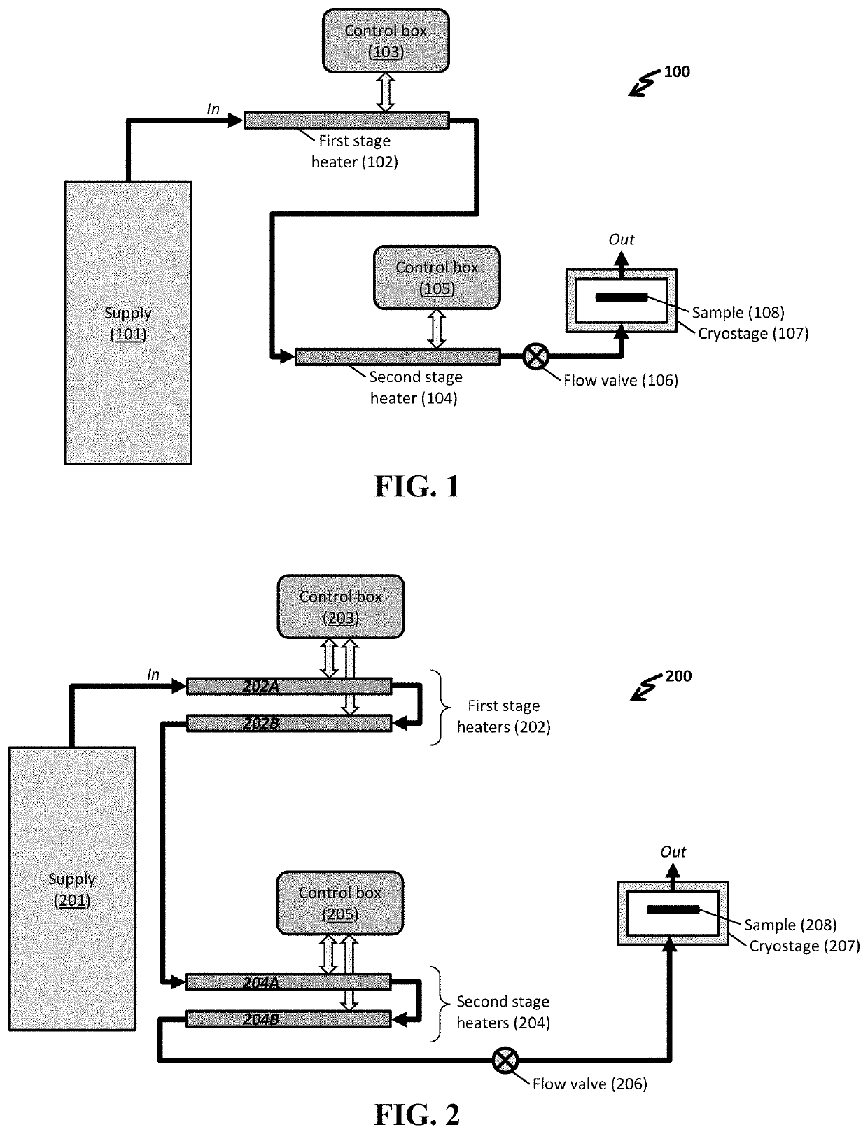
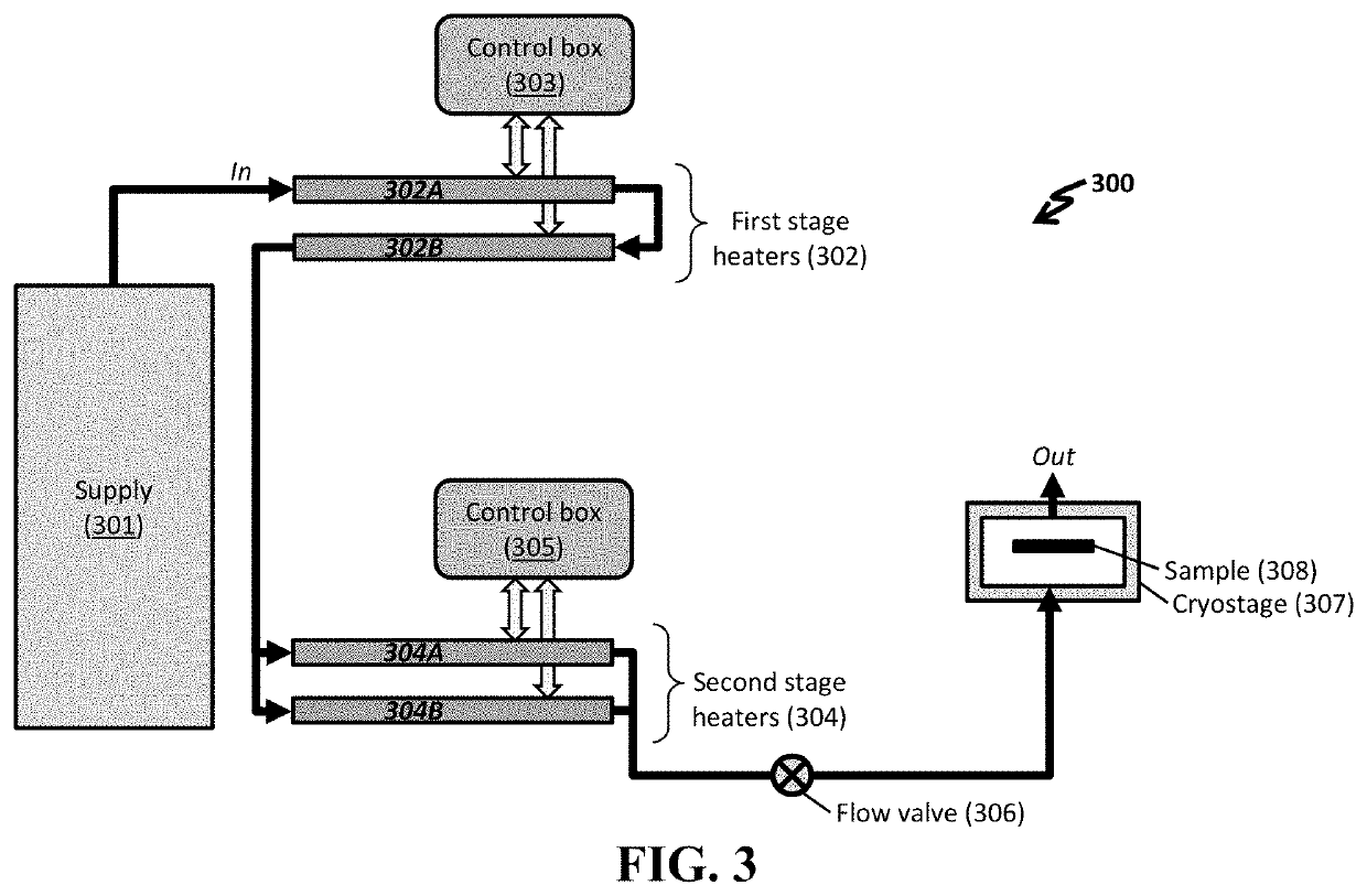
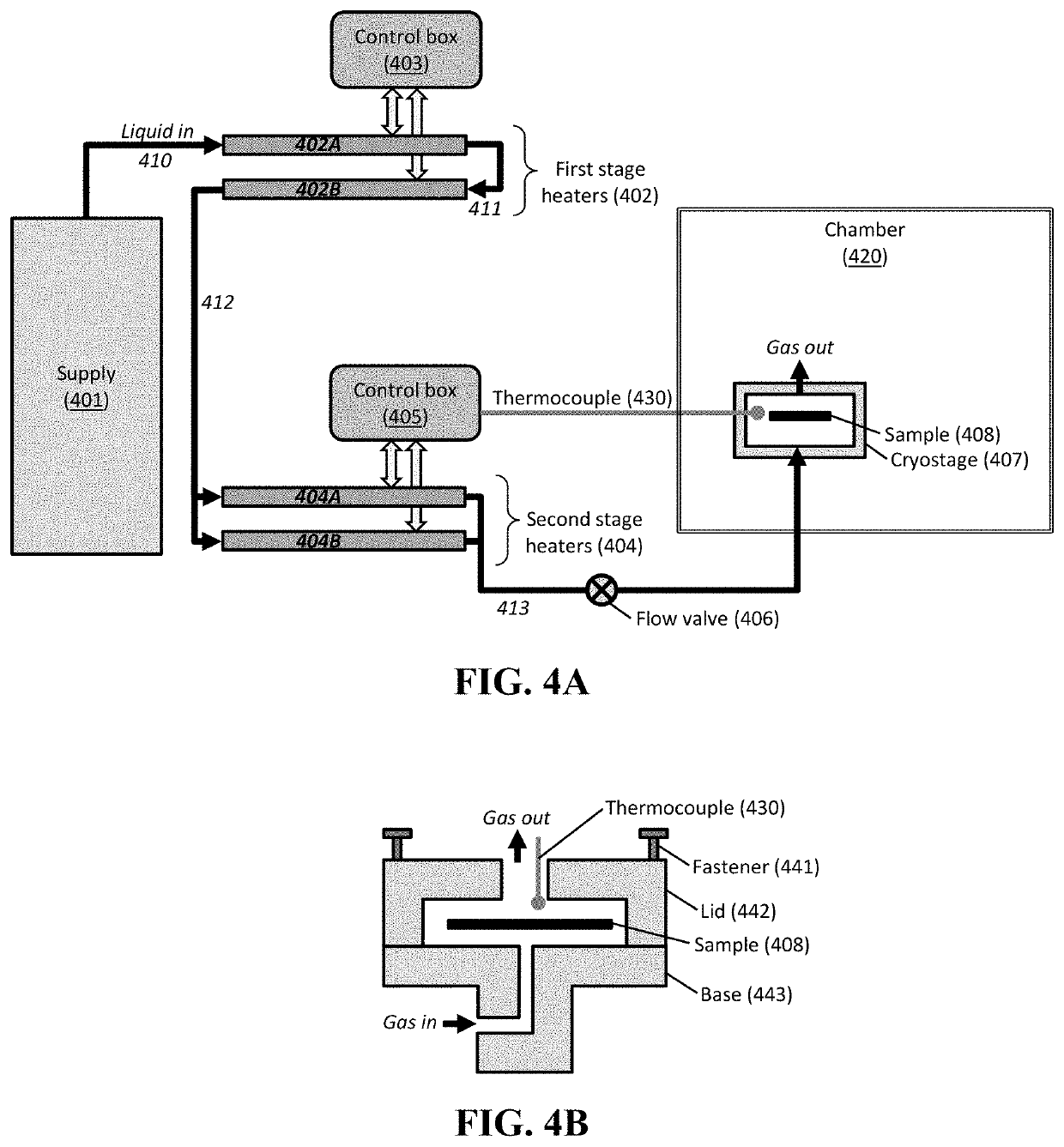
[0027]The cryogenic heating stage uses a liquid nitrogen supply to control the temperature of a test sample. The sample is indirectly heated or cooled by the gas from the T-type tube heaters, which heat or cool the liquid nitrogen between a large temperature range (e.g., a range of about 400° C.). The heaters are controlled by a custom built control system able to obtain precise and accurate temperatures.

[0028]The in situ cryogenic temperature-controlled rapid aging heater employs a cryogenic inert gas supply to heat and cool a sample (e.g., a test coupon) between of from about −200° C. to about 200° C. The inert gas supply can be any useful gas (e.g., liquid nitrogen or helium) at any useful temperature (e.g., cryogenic temperatures or room temperature). Further, temperature control is maintained without direct contact with the sample because a stream of heated gas or cooled gas is directed onto a surface of the sample. The cryostage uses tube gas heaters (e.g., totaling about 1900...


PUM


Abstract

The present invention relates to a cryogenic heating system including a plurality of stages to provide accurate temperature control. The system can be used to provide non-contact heating and cooling of a test sample by use of an inert fluid. Accurate temperature control can be maintained, e.g., by use of controllers to provide temperature feedback control.

Description

CROSS-REFERENCE TO RELATED APPLICATION[0001]This application claims the benefit of U.S. Provisional Application No. 62 / 367,986, filed Jul. 28, 2016, which is hereby incorporated by reference in its entirety.STATEMENT OF GOVERNMENT INTEREST[0002]This invention was made with Government support under Contract No. DE-NA0003525 awarded by the United States Department of Energy / National Nuclear Security Administration. The Government has certain rights in the invention.FIELD OF THE INVENTION[0003]The present invention relates to a cryogenic heating system including a plurality of stages to provide accurate temperature control. The system can be used to provide non-contact heating and cooling of a test sample by use of an inert fluid. Accurate temperature control can be maintained, e.g., by use of controllers to provide temperature feedback control.BACKGROUND OF THE INVENTION[0004]In situ heating and cooling of samples can be difficult to maintain and control. In particular, contact heatin...

Claims


Application Information

Patent Timeline
IPC IPC(8): H05B1/02F16K17/00G05D23/22G05D23/19F17C13/02F17C7/02
CPCF16K17/003G05D23/193F17C13/026F17C7/02G05D23/22H05B1/0247F17C2223/0161G05D23/1919H05B1/023
Inventor NATION, BRENDAN L.BABUSKA, TOMAS FARLEYGARFIELD, RAND
Owner NAT TECH & ENG SOLUTIONS OF SANDIA LLC
Why Eureka
Try Eureka