
Integrated circuit with built-in status monitoring unit and power supply device provided with said integrated circuit

a technology of integrated circuits and status monitoring devices, which is applied in the direction of measuring devices, electrical testing, instruments, etc., can solve the problems of inability to obtain electric potential, inability to share terminals of integrated circuits, and inability to reduce the dimensions of integrated circuits, so as to reduce the number of terminals, reduce the number of integrated circuits, and reduce the share of wiring parts

Active Publication Date: 2020-04-21
SANYO ELECTRIC CO LTD
View PDF10 Cites 1 Cited by
  • Summary
  • Abstract
  • Description
  • Claims
  • Application Information

AI Technical Summary

Benefits of technology

The present invention provides a solution for reducing the number of terminals and increasing the reliability of voltage detection in an integrated circuit. The invention includes switches for connecting adjacent connection terminals of the integrated circuit, which allows for the sharing of terminals for controlling to discharge a battery cell and detecting voltage. This reduces the number of terminals and allows for the integrated circuit to be downsized. Additionally, the invention ensures redundancy in voltage detection and keeps the integrated circuit reliable.

Problems solved by technology

Accordingly, when the number of terminals is large, even when the integrated circuit has sufficient space therein, the dimension of the integrated circuit cannot be reduced.
In this configuration, however, when disconnection, a short circuit, or the like, occurs in the shared wiring, the electric potential cannot be obtained.
In such a case, however, terminals of the integrated circuit cannot be shared.
As mentioned above, a conventional configuration has not been able to achieve only one of the reliability of status detection and downsizing of an integrated circuit.

Method used


Image

  • Integrated circuit with built-in status monitoring unit and power supply device provided with said integrated circuit
  • Integrated circuit with built-in status monitoring unit and power supply device provided with said integrated circuit
  • Integrated circuit with built-in status monitoring unit and power supply device provided with said integrated circuit

Examples


Embodiment Construction

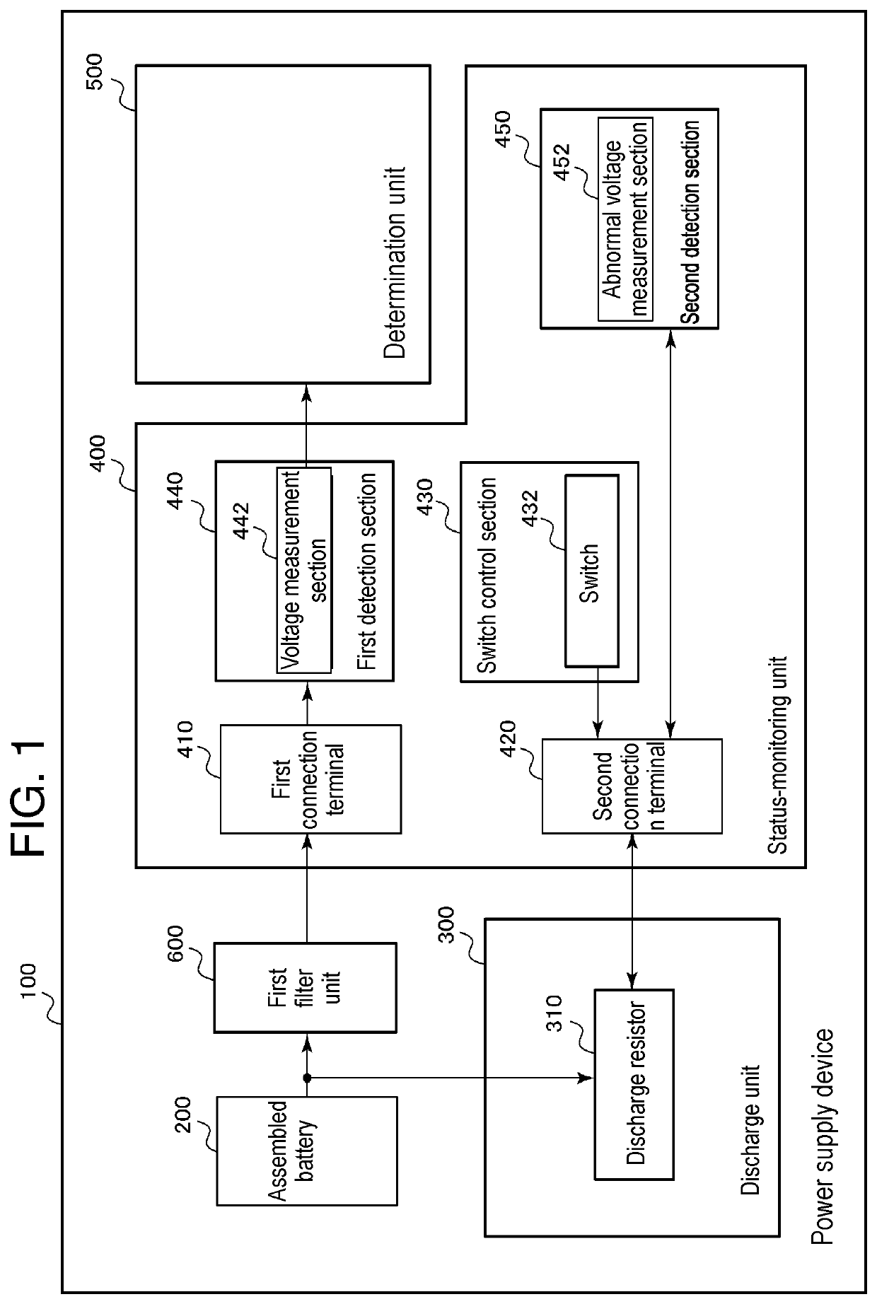
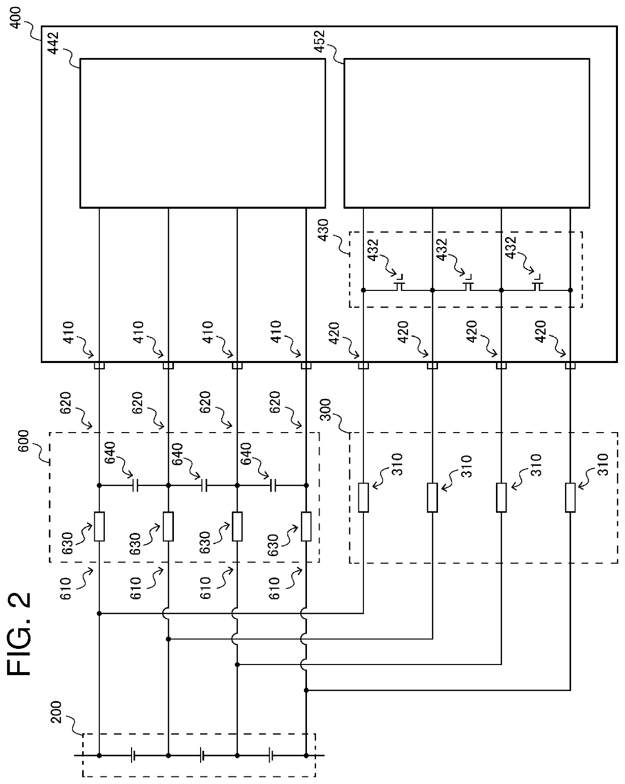
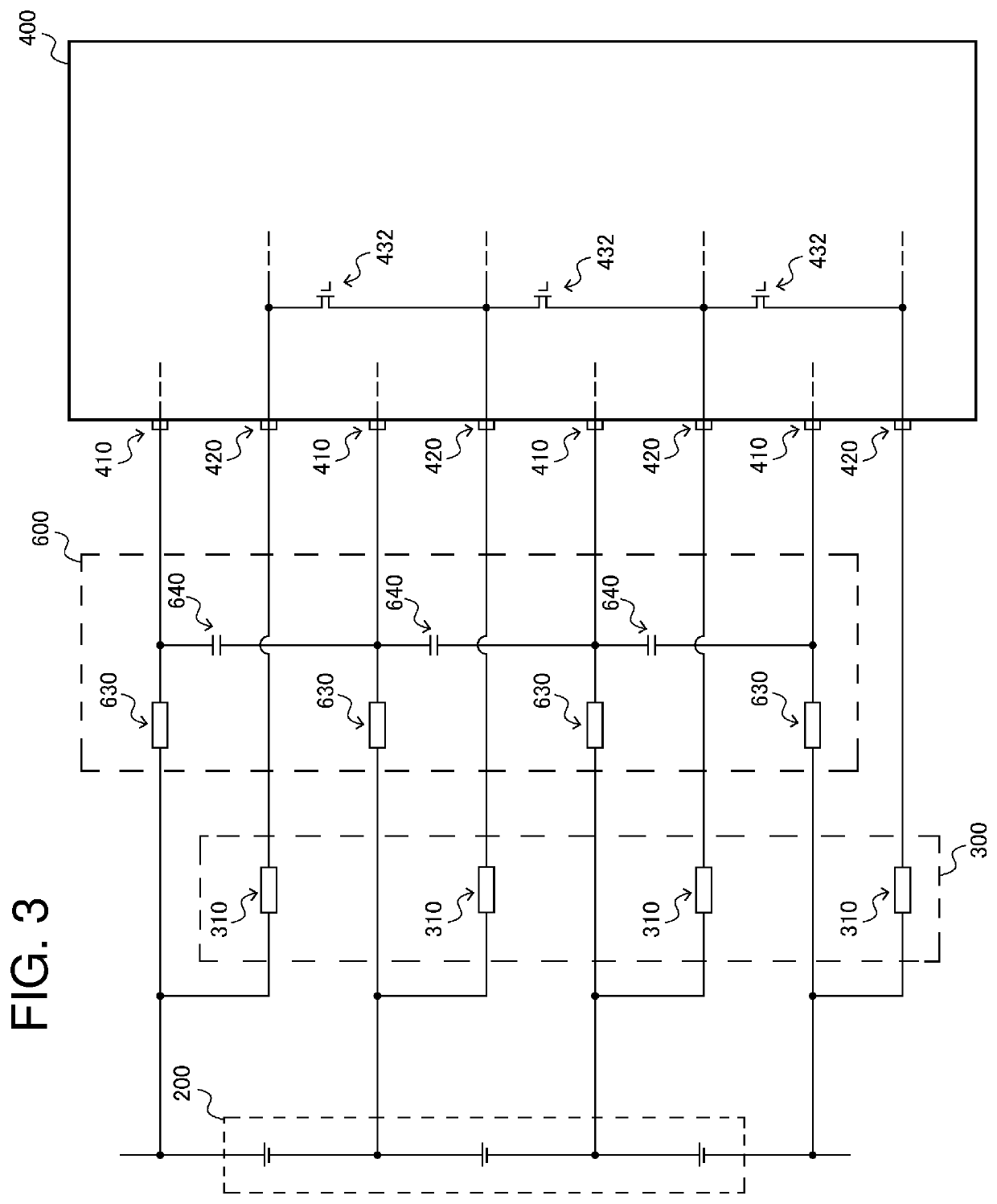
[0023]With reference to FIG. 1, an outline of an exemplary embodiment of the present invention is described. FIG. 1 is a diagram schematically showing an outline of power supply device 100 according to a first exemplary embodiment of the present invention. Power supply device 100 according to the first exemplary embodiment includes assembled battery 200 provided as a power supply to be mounted on a vehicle, and status-monitoring unit 400 for monitoring a status of assembled battery 200. Status monitoring unit 400 includes first connection terminal 410 and second connection terminal 420 to which an analog signal as an electrical signal is input, first detection section 440 connected to first connection terminal 410, and second detection section 450 connected to second connection terminal 420. Status monitoring unit 400 is further provided with switch control section 430 including switch 432 connected to second connection terminal 420. Switch control section 430 controls a working sta...


PUM

PropertyMeasurementUnit
resistanceaaaaaaaaaa
frequencyaaaaaaaaaa
voltageaaaaaaaaaa

Abstract

A integrated circuit includes a plurality of first connection terminals (410) and second connection terminals (420) for receiving an input of electrical signals, a first detection section, a second detection section, a plurality of switches (432), and a switch control section (430). The first detection section is connected to first connection terminals (410) and obtains input electrical signals. The second detection section is connected to second connection terminals (420). Each switch (432) connects adjacent second connection terminals (420) among second connection terminals (420) to each other, and are connected to each other in series. Switch control section (430) controls to turn off switches (432) and allows electrical signals input to second connection terminals (420) to be input to the second detection section, and controls to turn on any switch among switches (432) to bring adjacent second connection terminals (420) into electrical continuity.

Description

CROSS-REFERENCE TO RELATED APPLICATIONS[0001]This application is a U.S. national stage application of the PCT International Application No. PCT / JP2015 / 003363 filed on Jul. 3, 2015, which claims the benefit of foreign priority of Japanese patent application No. 2014-218788 filed on Oct. 28, 2014, the contents all of which are incorporated herein by reference.TECHNICAL FIELD[0002]The present invention relates to an integrated circuit having a built-in status-monitoring unit for monitoring a status of a plurality of battery cells connected to each other in series and a power supply device including the integrated circuit.BACKGROUND ART[0003]A power supply device including an assembled battery configured of a plurality of battery cells includes a status-monitoring unit for monitoring a status of the battery cells in order to avoid abnormal states such as over-charge and over-discharge of the battery cells. The status-monitoring unit detects data such as a voltage, an electric current, a...

Claims


Application Information

Patent Timeline
Patent Type & Authority Patents(United States)
IPC IPC(8): G01R31/396H01M10/48G01R31/3835
CPCH01M10/482G01R31/396G01R31/3835Y02E60/10
Inventor ASAKURA, JUNFURUKAWA, KIMIHIKOMATSUBARA, TOMOYUKI
Owner SANYO ELECTRIC CO LTD
Learn More