Flash memory testing according to error type pattern

a flash memory and type pattern technology, applied in error detection/correction, digital storage, instruments, etc., can solve problems such as data read error, flash memory has a limit on the number of erase cycles, and the charge of the floating gate of memory cells in the same block or in the adjacent block, so as to reduce the number of searching the retry table, improve the speed of reaction, and reduce the access loading of flash memory

Active Publication Date: 2020-04-21
SOLID STATE STORAGE TECH CORP
View PDF7 Cites 0 Cited by
  • Summary
  • Abstract
  • Description
  • Claims
  • Application Information

AI Technical Summary

Benefits of technology

[0008]In summary, the storage system and the storage method shown in the present invention can define various error type patterns in advance through the retry table. When a data access error occurs, the control circuit can test each of the retry set of voltage shift values in sequence until the voltage shift value corresponding to the current error type is found, and according to the current error type pattern, the corresponding error recovery action will be performed. For example, the control circuit moves the repaired data to other memory blocks to avoid using bad memory blocks, or move the repaired data to the cache memory to reduce the access loading of the flash memory, or based on the adjusted accessing voltage to read future data in the same page. That is, reading the data in the same page of the flash memory, the control circuit can directly read this data with the adjusted accessing voltage and reduce the number of searching the retry table. Therefore, the present invention achieves improving the speed of reaction in the event of an error in the storage system and provides a repair mechanism, thereby increasing the overall performance.

Problems solved by technology

However, the flash memory has a limit on the number of erase cycles.
By the way, if the same page of data in the flash memory is read too frequently in a period of time, it will result in a change in the charges of the floating-gates of memory cells in the same block or in the adjacent block.
A data read error maybe occurred while the data was being accessed under such conditions.
Therefore, how to provide a storage system and a storage method that can provide a better error-recovery response when the storage system is encountered a read error and then increase the overall performance has become an urgent problem in the art.

Method used


Image

  • Flash memory testing according to error type pattern
  • Flash memory testing according to error type pattern
  • Flash memory testing according to error type pattern

Examples


Embodiment Construction

[0014]Reference will now be made in detail to the present embodiments of the invention, examples of which are illustrated in the accompanying drawings. Wherever possible, the same reference numbers are used in the drawings and the description to refer to the same or like parts.

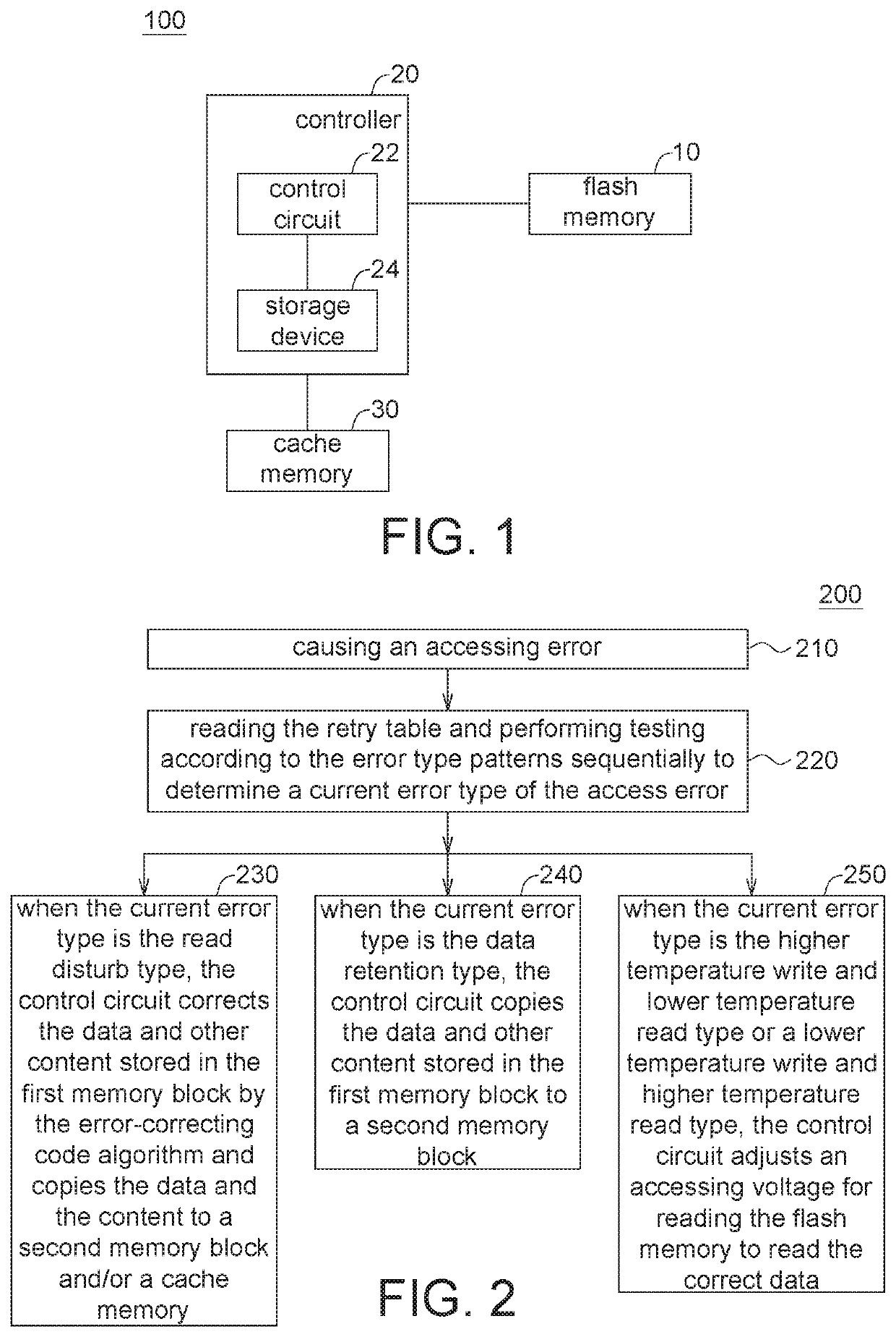
[0015]It will be understood that, although the terms “first,”“second,”“current,” etc. may be used herein to describe various elements, these elements should not be limited by these terms. These terms are only used to distinguish one element from another. Reference is made to FIG. 1 and FIG. 2. FIG. 1 is a block diagram of a storage system 100 according to one embodiment of the present invention. FIG. 2 is a flowchart of a storage method 200 according to one embodiment of the present invention.

[0016]In one embodiment, the storage system 100 comprises a flash memory 10 and a controller 20. The controller 20 further comprises a control circuit 22 and a storage device 24. The controller 20 is coupled to the flash ...


PUM


Abstract

A storage method comprises storing a retry table; wherein the retry table recites a plurality of error type patterns, the error type patterns comprises a plurality of default error types; accessing data stored in the flash memory; wherein an access error caused when a control circuit reads the data, the control circuit reads the retry table and performs testing according to the error type patterns sequentially to determine a current error type of the access error, and the control circuit performs an adjusted accessing action according to the current error type.

Description

[0001]This application claims the benefit of People's Republic of China application Serial No. 201711395467.0, filed on Dec. 21, 2017, the subject matter of which is incorporated herein by reference.BACKGROUNDField of Invention[0002]The present invention relates to a storage system and a storage method. More particularly, the present invention relates to a storage system and a storage method where the flash memories are used as the mass data storage device.Description of Related Art[0003]Flash memory is a type of non-volatile memory that allows user to erase data or write data multiple times during an operation. Flash memory stores data in a memory cell array composed of floating-gate transistors. In a single-level cell (SLC) device, each cell stores only 1-bit information. Multi-level cell (MLC) devices use a variety of charge levels to allow each cell to store more than one bit (for example, two bits) of data.[0004]However, the flash memory has a limit on the number of erase cycle...

Claims


Application Information

Patent Timeline
Patent Type & Authority Patents(United States)
IPC IPC(8): G06F11/07G11C7/04G11C29/10G11C16/34G11C29/50G06F11/263
CPCG11C29/50004G11C29/10G06F11/0727G06F11/263G11C29/50016G11C16/3404G11C7/04G06F11/079G11C16/10G11C2207/2245G11C29/021G11C29/028G11C29/52G11C2029/5002G11C2029/5004G06F11/1072G11C16/26
Inventor WU, TSUNG-HUNGLIN, SIN-YU
Owner SOLID STATE STORAGE TECH CORP
Why Eureka
Try Eureka