
Robot joint and robot including the same

a robot joint and robot technology, applied in the field of robot joints, can solve the problems of reducing the lifetime of cables, unplanned shutdown, and the inability of cables to bear too much bending and twisting for a long time, and achieve the effect of long lifetime and large rotation rang

Active Publication Date: 2020-04-28
ABB (SCHWEIZ) AG
View PDF9 Cites 23 Cited by
  • Summary
  • Abstract
  • Description
  • Claims
  • Application Information

AI Technical Summary

Benefits of technology

The invention proposes a robot joint that is small, can rotate widely, and is long-lasting. The technical effect of the patent is that it provides a cost-effective way to create a compact robot joint that has a larger rotation range and longer lifetime.

Problems solved by technology

But these cables cannot bear too much bending and twisting for a long time.
In addition, improper routing structures may cause cables and hoses bending in small radius, twisting in small length, or sliding on coarse surfaces, all of which will reduce the lifetime of cables and lead to unexpected shutdown.

Method used


Image

  • Robot joint and robot including the same
  • Robot joint and robot including the same
  • Robot joint and robot including the same

Examples


Embodiment Construction

[0020]Reference will now be made in detail to several embodiments of the present invention, example of which are illustrated in the accompanying figures. It is noted that wherever practicable similar or like reference numbers may be used in the figures, and may indicates similar or like functionality. The figures depict embodiments of the present invention for purposes of illustration only. One skilled in the art will readily recognize from the following description that alternative embodiments of the structures and methods illustrated herein may be employed without departing from the principles of the present invention described therein.

[0021]A flexible printed circuit (FPC) board typically refers to a circuit or wiring structure mounted on a flexible plastic substrate, such as polyimide or polyester film. A type of FPC board contains one or more printed wires for interconnecting electronic components or electronic assemblies either directly or by means of connectors. An FPC board ...


PUM


Abstract

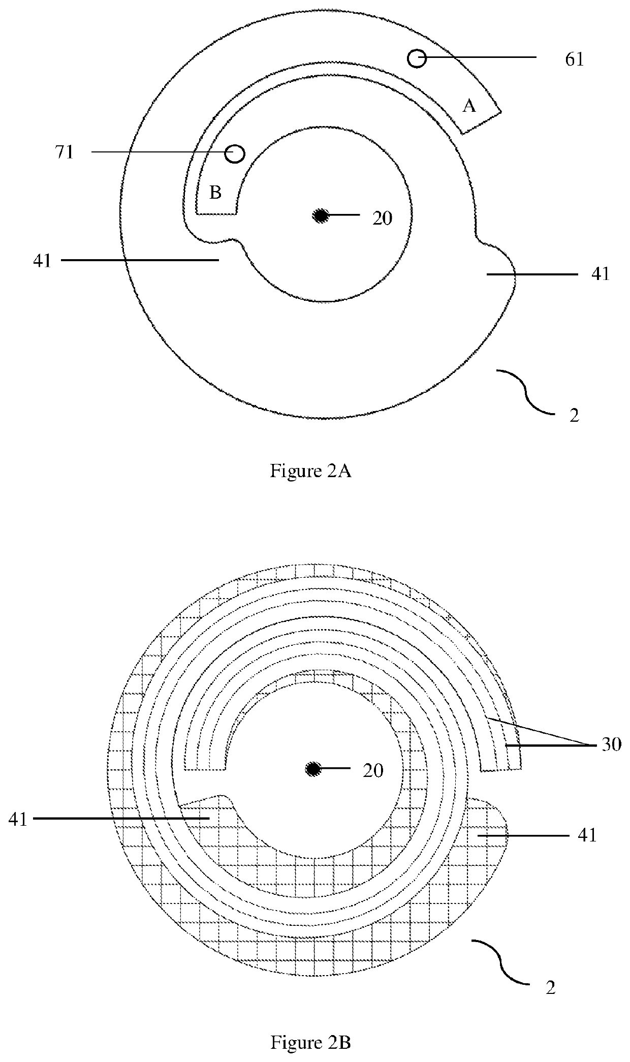
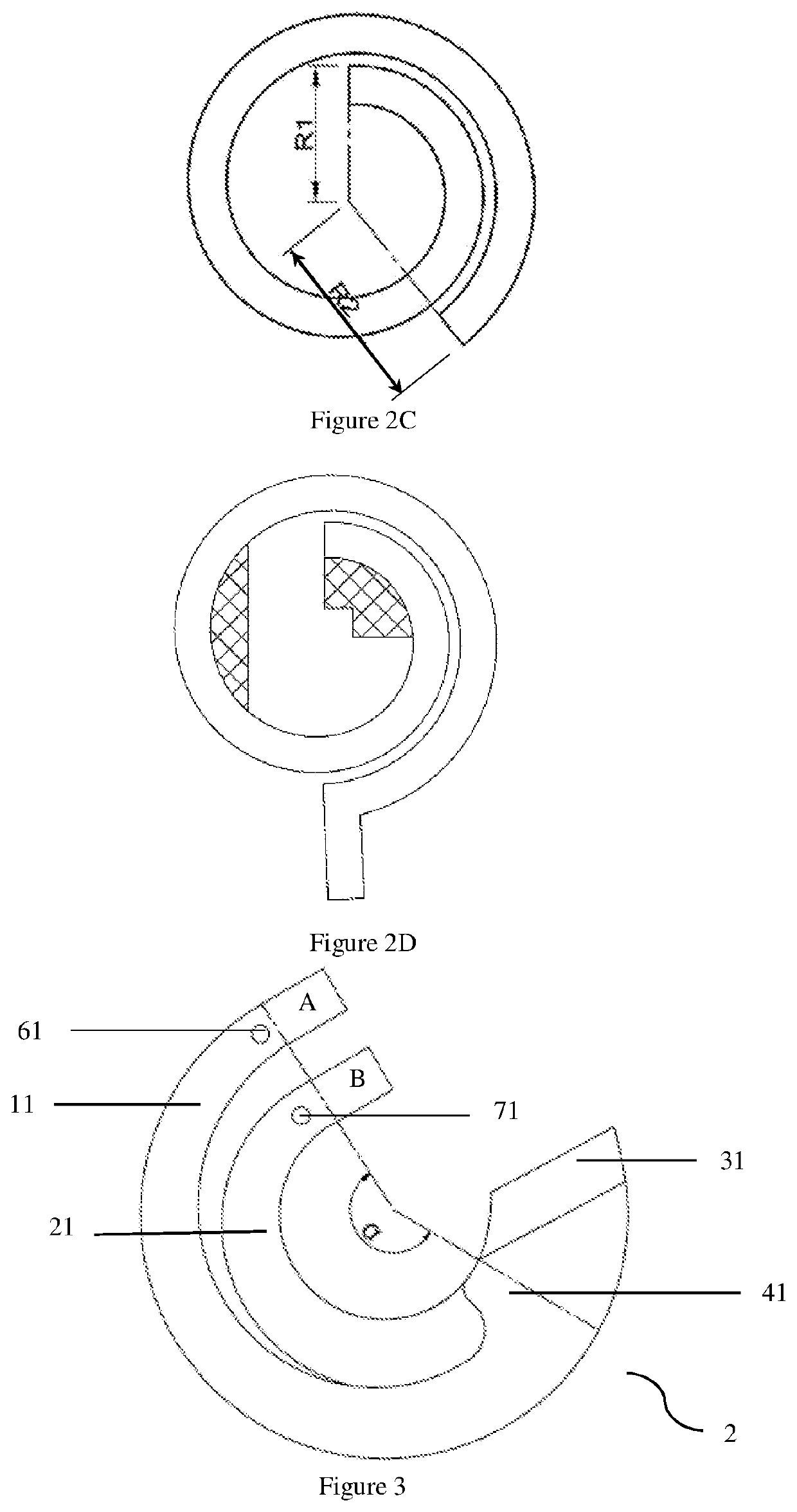
A robot joint and a robot using the robot joint is provided. The robot joint includes a first part and a second part configured to be rotatable with each other around a joint axis. A flexible printed circuit board is further included with a first fixing point and a second fixing point respectively fastened to the first part and the second part. The flexible printed circuit board is spiral-shaped prior to bending. With the relative rotation of the first part and the second part, the flexible printed circuit board is bent at various bending portions. This makes the robot joint more compact with a larger rotation range and a long lifetime in a cost effective way.

Description

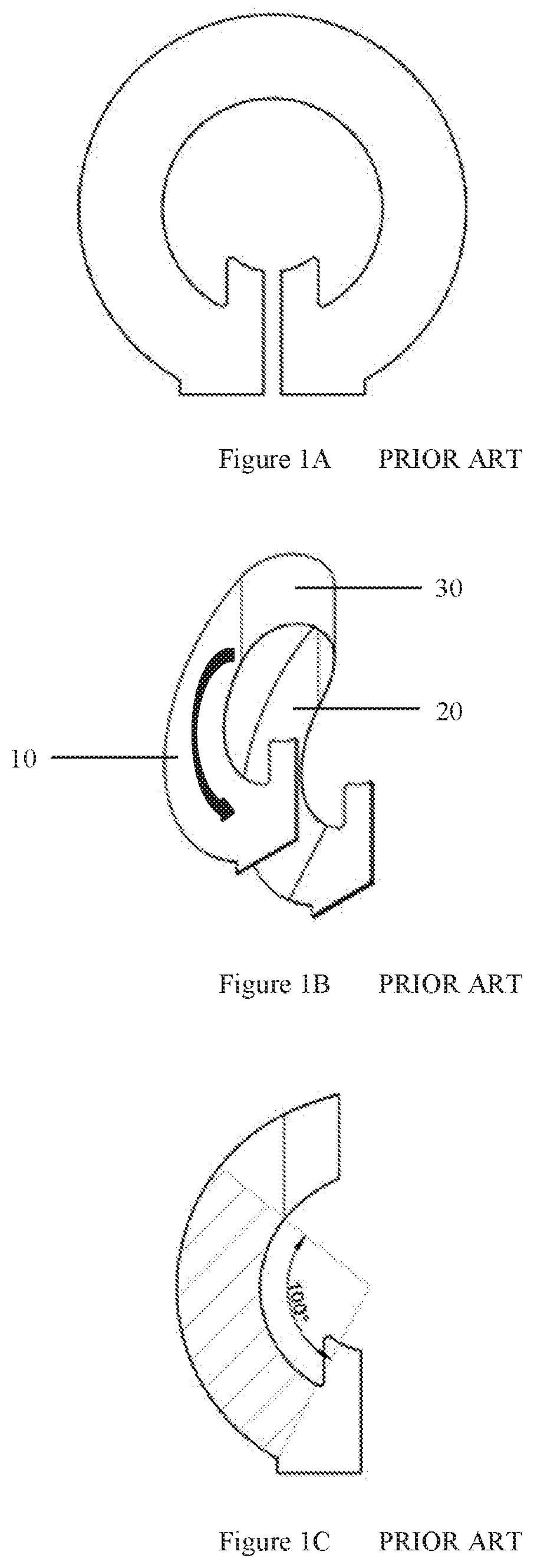
TECHNICAL FIELD[0001]The present invention relates to a robot joint, and more particularly, to a rotary joint of robot which includes a flexible printed circuit board and a robot including the same.BACKGROUND ART[0002]For industrial robots, especially the ones designed to work in limited and complex workspaces, flexibility and compactness are two major design requirements. Generally, the larger the rotation ranges of robot joints are, the more flexible the robot is. Usually, cables and hoses are routed within the robot joints to prevent interfering with surroundings. But these cables cannot bear too much bending and twisting for a long time. In addition, improper routing structures may cause cables and hoses bending in small radius, twisting in small length, or sliding on coarse surfaces, all of which will reduce the lifetime of cables and lead to unexpected shutdown.[0003]One common solution is to use flexible printed circuit (FPC) boards inside the robot joints to transmit power a...

Claims


Application Information

Patent Timeline
Patent Type & Authority Patents(United States)
IPC IPC(8): B25J19/00H01R35/02B25J17/00B25J17/02H05K1/03
CPCB25J19/0025B25J17/00B25J17/02B25J19/0029H01R35/025H05K1/0393Y10T74/20311
Inventor CAO, KAIYUANCAO, XIAODONGHA, YUNZHU, ZHUSHA, JIAJIE
Owner ABB (SCHWEIZ) AG
Learn More