Method for monitoring linear dimensions of three-dimensional objects

a three-dimensional object and linear measurement technology, applied in the field of measuring instruments, can solve the problems of inability to foresee or take into account in advance image distortion, poor accuracy, and limitations of the previously used method and the device use, and achieve the effect of expanding the range of methods and effective and efficient methods

Active Publication Date: 2020-05-12
ARTEC EURO S A R L
View PDF74 Cites 1 Cited by
  • Summary
  • Abstract
  • Description
  • Claims
  • Application Information

AI Technical Summary

Benefits of technology

[0013]The object of this invention is therefore to create an effective and efficient method of controlling linear dimensions of three-dimensional objects, as well as to expand the range of methods for controlling linear dimensions of three-dimensional objects.
[0014]The technical result ensuring that the object is achieved consists of simplification and complete automation of the process of controlling linear dimensions of three-dimensional objects, reduction of the measurement process duration and nearly complete elimination of errors in the event of mechanical oscillations arising in positions of the equipment (projection unit and cameras) in relation to the measurement object, as the projection unit and cameras are executed as a portable tool in a single housing.

Problems solved by technology

The disadvantages of the known method are a high error rate caused by the fact that when optical radiation modulated along one of the coordinates through a transparency filter with a non-varied regular structure is directed at the controlled object surface, it is impossible to foresee or take into account in advance the image distortions caused by different reflective properties of the surface and deep recesses, which cannot be identified without any prior information about the macrostructure of the controlled object surface.
The limitation of the previously used method and the devices using it is poor accuracy related to the impossibility of unambiguous interpretation of the gaps in the image of the bands distorted by the contour of the controlled object surface, or by through holes, or by a low spectral reflectance value depending on the color of some area of the controlled object surface.
If the controlled object is a total of local components, e.g. a set of turbine blades, reconstruction of such object's topology and the subsequent control of its linear dimensions using the above method are impossible.
The limitations of this method consist of the complexity of the device using it and the process duration requiring considerable time for measurements and leaving room for errors in the event of mechanical oscillations of the equipment (projection unit and camera) positions.
The limitations of this method also consist of the complexity of the device using it and the process duration requiring considerable time for measurements and leaving room for errors in the event of mechanical oscillations of the equipment (projection unit and camera) positions.
The limitation of this method is the long time required for searching through all the possible pairs of bands and the long correlation algorithm running time.

Method used


Image

  • Method for monitoring linear dimensions of three-dimensional objects
  • Method for monitoring linear dimensions of three-dimensional objects
  • Method for monitoring linear dimensions of three-dimensional objects

Examples


Embodiment Construction

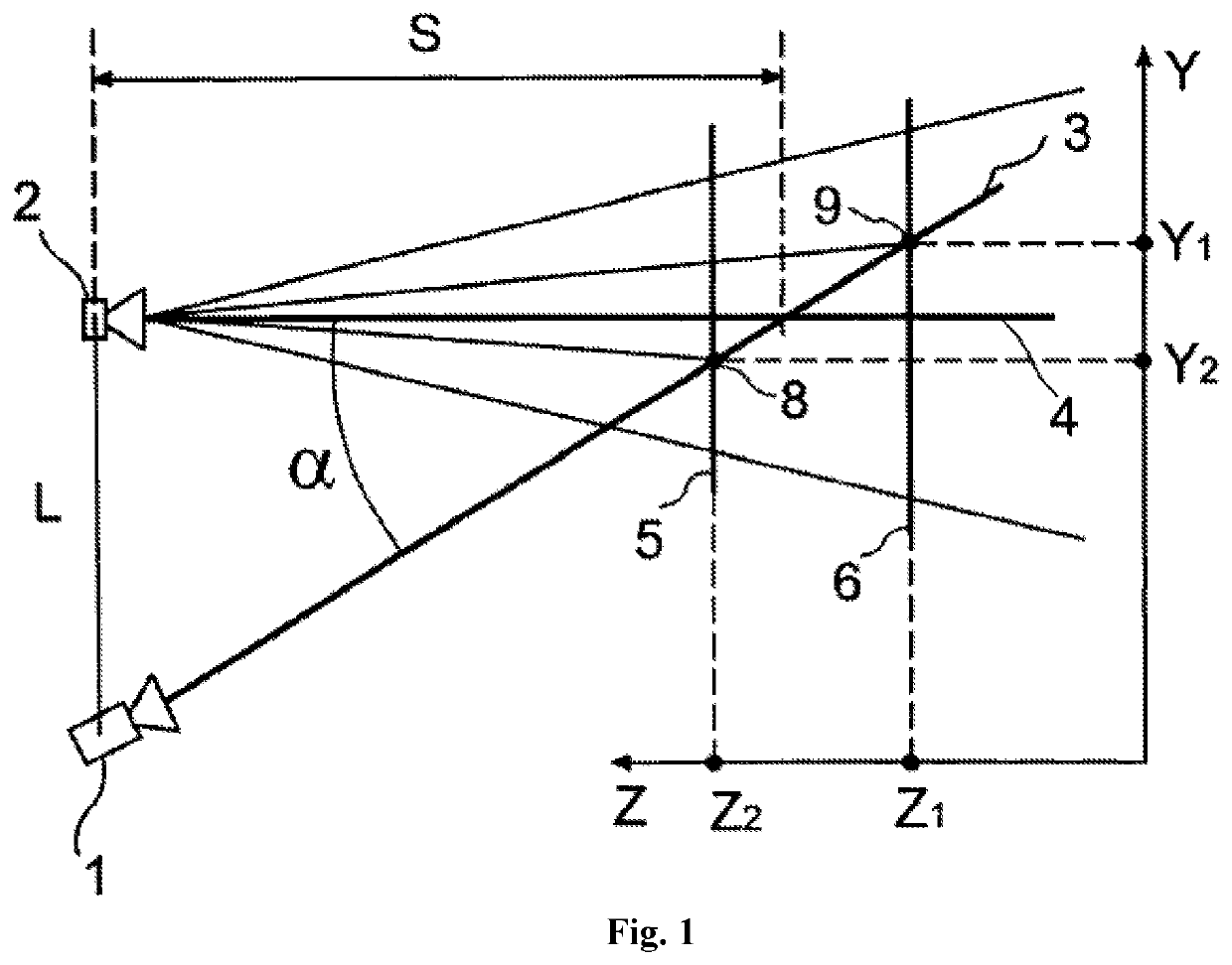
[0029]FIG. 1 shows a device comprised of projection unit 1 which projects the predetermined image onto the object and the camera 2 recording and transmitting to the computer (not shown) the light emitted by projection unit 1 and reflected from the object, at a certain triangulation angle α (angle between the central beam of the projection unit 3 and central beam 4 of camera 1.

[0030]The distance L between the camera and the projection unit is called the base. The base can be chosen as follows.

[0031]L=s*tg α, where s is the distance from the projection unit to the intersection point of the central beams of the projection unit and the camera (m).

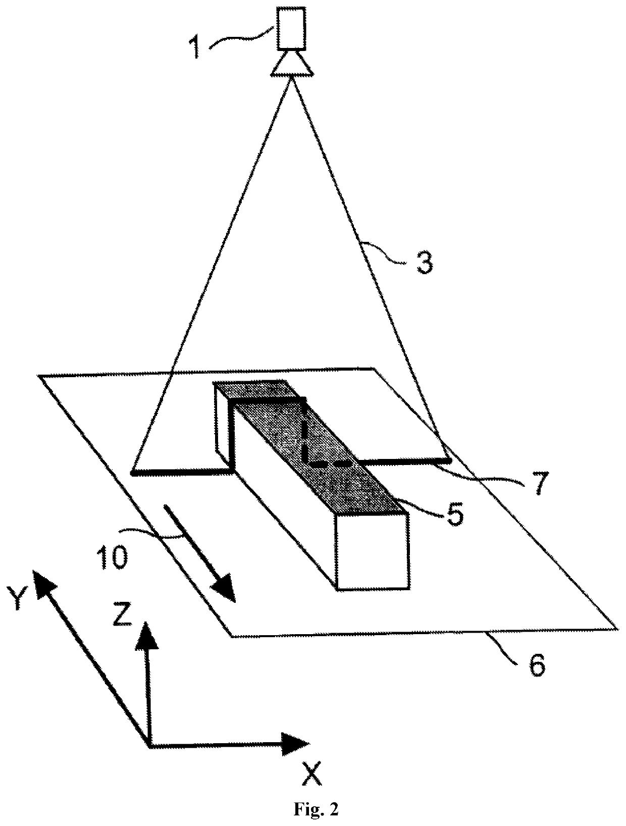
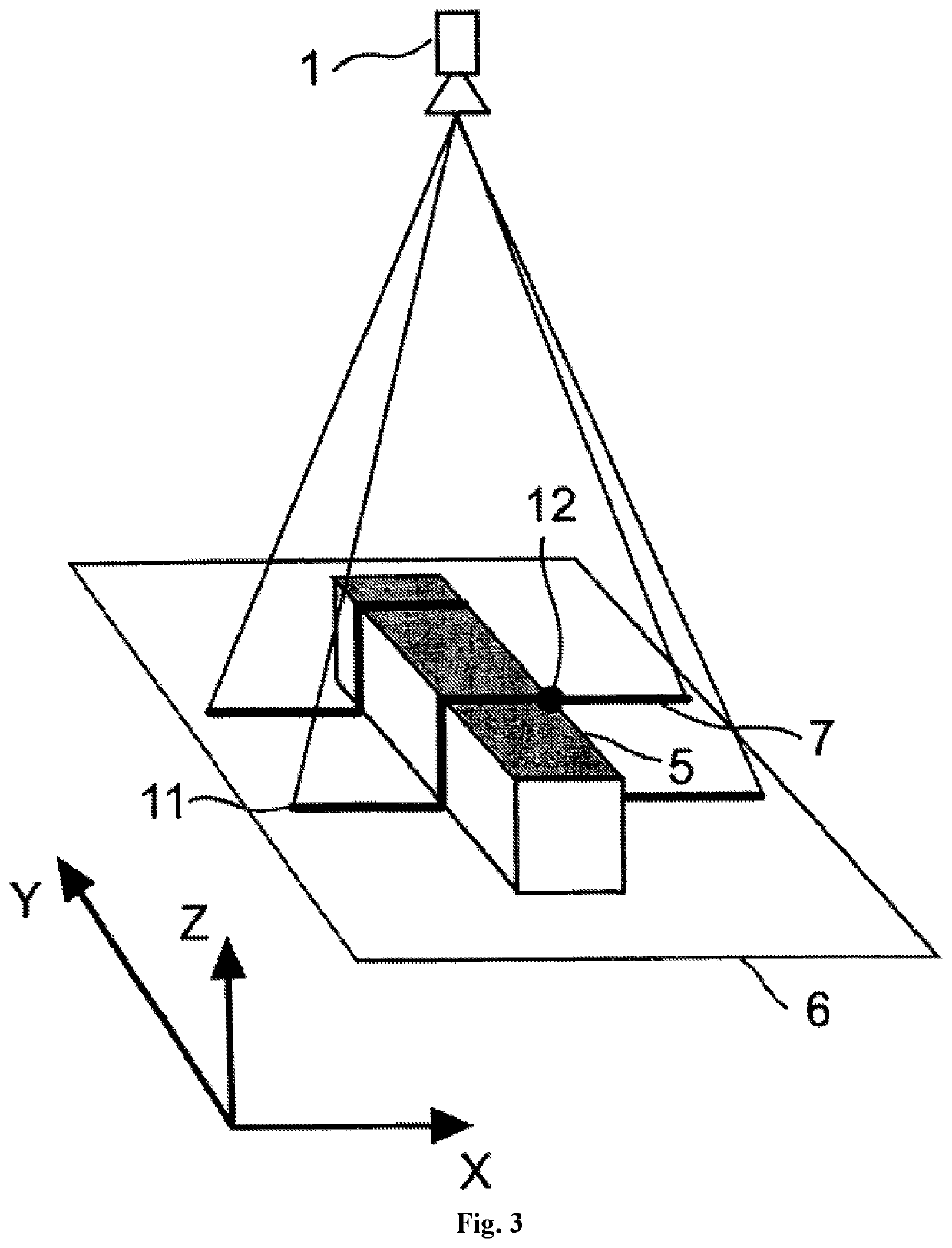
[0032]In the simplest case, projection unit 1 projects one horizontal band 3 which coincides with the central beam of the projection unit in FIG. 1. FIG. 2 is a view from camera 2. FIG. 2 shows the way band 3 is distorted due to the curvature of the object shown as planes 5 and 6, and a trace 7 of the reflected band 3 is seen in the image of ca...


PUM


Abstract

A method of 3D measurement is performed using a first camera and a second camera located at different distances from the projector. The method includes projecting a known projection pattern that includes at least two non-crossing lines to form a first band and a second band on a surface of an object. The method includes recording first and second images of the object using the first and second cameras, respectively. The method includes determining a first longitudinal coordinate of a first point within the first band and a first vertical coordinate of the first point within the first band; determining a second longitudinal coordinate of the first point within the first band; and determining a second vertical coordinate of the first point within the first band. The method includes determining a final vertical coordinate of the first point by comparing the first longitudinal coordinate to the second longitudinal coordinate.

Description

FIELD OF THE INVENTION[0001]The invention pertains to measuring instruments and can be used for 3D measurements with an adequate accuracy and display of three-dimensional object contours by observing a known projected pattern at various triangulation angles.DESCRIPTION OF THE STATE OF THE ART[0002]A previously known method for controlling linear dimensions of three-dimensional objects based on three coordinates consists of forming a probing structured backlighting on the surface of the controlled object by projecting on the surface of the controlled object a beam of light, characterized by modulated spatial intensity, registering of the image of the probing backlight pattern distorted by the topography of the controlled object's surface and determining the height of the controlled object's surface topography with a digital electronic computer measuring the topographic height based on the distortion value of the probing backlighting pattern, and calculating the other two coordinates ...

Claims


Application Information

Patent Timeline
Patent Type & Authority Patents(United States)
IPC IPC(8): G01B11/00G01B11/25
CPCG01B11/25G01B11/002G01B11/2545
Inventor KLIMOV, ANDREI V.LOMAKIN, ALEKSANDR GEORGIEVICHSUKHOVEY, SERGEY V.GUSEV, GLEB A.YUKHIN, ARTEM L.
Owner ARTEC EURO S A R L
Why Eureka
Try Eureka