Electric pedal for automobiles

a technology for automobiles and pedals, applied in the direction of gearing, mechanical control devices, instruments, etc., can solve the problems of high manufacturing precision, high manufacturing cost, and difficulty in ensuring such a high manufacture precision, so as to reduce the possibility of abnormal sound and reduce the manufacturing cost

Active Publication Date: 2020-05-12
ANHUI AGGEUS AUTO TECH CO LTD
View PDF21 Cites 15 Cited by
  • Summary
  • Abstract
  • Description
  • Claims
  • Application Information

AI Technical Summary

Benefits of technology

[0012]In order to solve the disadvantages and deficiencies of the retractable pedal in the prior art, the present invention provides an electric pedal for automobiles. A driving shaft of a driving mechanism of the electric pedal is directly connected to a first transmission mechanism of a driving support, so the conventional gear transmission mechanism is omitted, the manufacture cost is reduced, and the possibility of occurrence of abnormal sound is reduced. When the pedal is in the retracted state, its upper surface is substantially parallel to the ground, without any horizontally outward component force. This ensures that the pedal can retract in place.
[0049]1. The arrangement of a special support structure ensures that the pedal is horizontal or approximately horizontal when in the retracted state and the stretched state, and that the pedal can retract in place. In this way, the pedal is prevented from stretching during the running of a vehicle, which otherwise may influence the passage of the vehicle body through a road and get into danger.
[0050]2. The output shaft of the driving mechanism is used as a driving shaft in place of a conventional gear transmission mechanism; the driving mechanism is equipped with a gearbox and has a good self-locking function.
[0052]4. All the transmission shafts are fixed to the corresponding support arms or driving arms by the first locking bolt to form a whole. Therefore, it is firmer than the simple close fitting of the transmission shafts within the shaft holes on the corresponding support arms or driving arms.
[0053]5. Bushings made of special material are provided between all the transmission shafts and the shaft holes and between the driving shaft and the shaft holes. The bushings have a good self-lubrication effect, so abnormal sound resulted from poor lubrication effect after long-term operation is avoided.

Problems solved by technology

However, due to the unreasonable design of the retractable support structure, the retractable pedal in the prior art has various disadvantages and deficiencies.
1. When the pedal is in the retracted state, the driven support structure will fall down or become loose since it is not tight enough.
Consequently, a high manufacture precision is required and it is difficult to ensure such a high manufacture precision.
The cost for manufacturing such a gear transmission mechanism is high.
Furthermore, abnormal sound is likely to occur in gear transmission.
3. The driving shaft and the driving arm may slide relatively due to infirm connection therebetween (in most cases, the driving shaft may rotate relative to the driving arm), resulting in abnormal sound and noise.
As a result, the service life of the product may be influenced and abnormal sound may occur.
5. Since a copper-plated iron bushing is used between the transmission shaft and the corresponding shaft hole, the lubrication effect maybe deteriorated after long-term wear, and abnormal sound may occur along with the continuous deterioration of the lubrication effect.
As a result, the pedal has to be removed in the event of vehicle failures.
It is inconvenient for maintenance.

Method used


Image

  • Electric pedal for automobiles
  • Electric pedal for automobiles
  • Electric pedal for automobiles

Examples


Embodiment Construction

[0068]The exemplary implementations of the present invention will be described below in detail with reference to the accompanying drawings. The description of the exemplary implementations is merely illustrative, rather than limiting the present invention and applications or usages thereof.

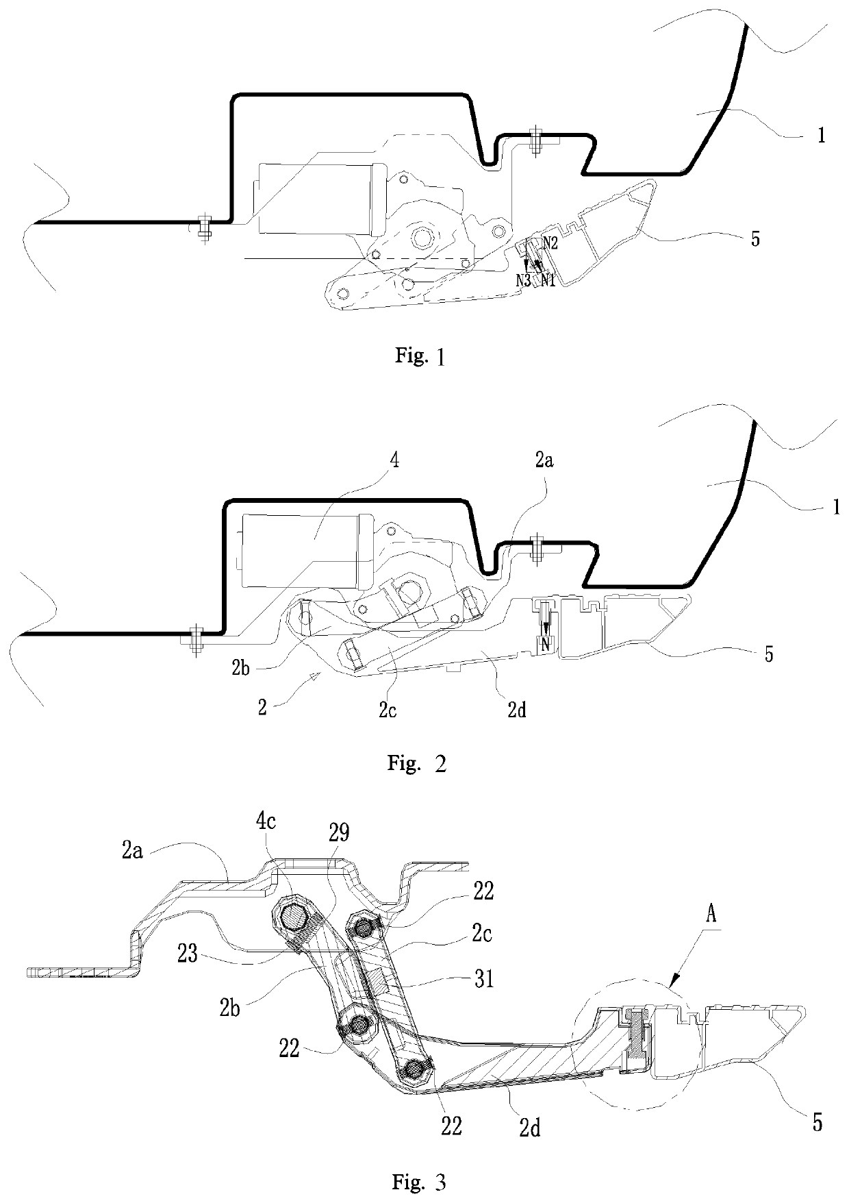
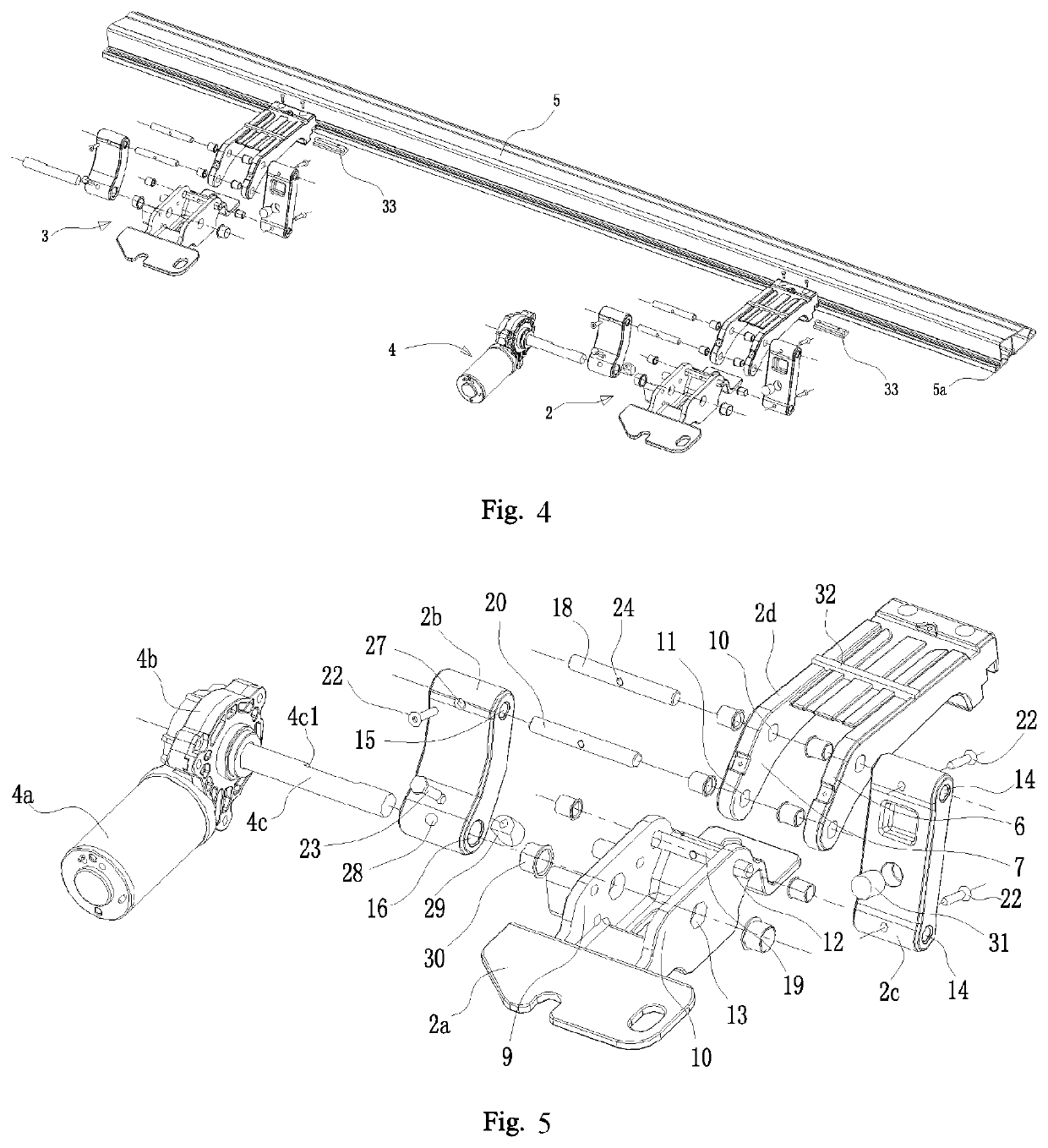
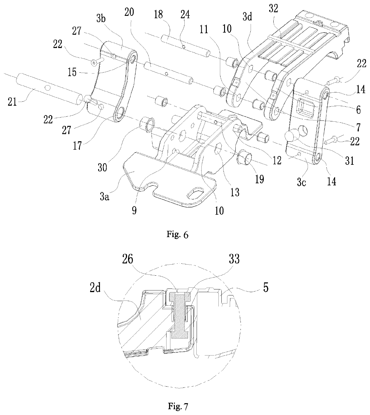
[0069]In an embodiment of the present invention, a retractable pedal for automobiles is provided. The retractable pedal has a special support structure design, wherein a driving support 2 is directly connected to a driving shaft 4c of a driving mechanism 4. That is, the output shaft of the motor serves as the driving shaft 4c, and the gear transmission mechanism is omitted. This overcomes the defect that it is likely to generate abnormal sound in the conventional design where a pedal 5 is driven to stretch and retract by a gear transmission mechanism. Since the complicated gear transmission mechanism is omitted, the manufacture cost for the whole pedal for automobiles is reduced greatly. Since a d...


PUM


Abstract

Provided is a retractable pedal for an automobile. The pedal comprises a driving support (2), a drive mechanism (4) and a footrest (5), wherein both the driving support (2) and the drive mechanism (4) are installed on the same side of the bottom of an automobile body; the driving support (2) comprises a first transmission mechanism and a first connecting rod (2d), and the front end of the first connecting rod (2d) is fixedly connected to the footrest (5); the first transmission mechanism drives the first connecting rod (2d) to expand and retract; the pedal further comprises at least one driven support (3) which synchronously moves with the driving support (2). According to this pedal, a traditional gear transmission mechanism is omitted so as to reduce manufacturing costs and reduce the generation of abnormal sounds, and the footrest can be ensured to retract in place.

Description

CROSS-REFERENCE[0001]This application is a continuation of PCT Application No. PCT / CN2017 / 114593, filed Dec. 5, 2017, which claims priority to Chinese Patent Application No. 2016111282496, filed on Dec. 9, 2016 and entitled ELECTRONIC PEDAL FOR AUTOMOBILES, the contents of which are incorporated herein by reference in its entirety.TECHNICAL FIELD[0002]The present invention belongs to the technical field of pedals for automobiles, and particularly relates to a retractable pedal for automobiles.BACKGROUND OF THE PRESENT INVENTION[0003]The related technical background of the present invention will be described below, but these descriptions do not necessarily constitute the prior art to the present invention.[0004]Pedals for vehicles include fixed pedals and retractable pedals. As its name implies, a fixed pedal cannot retract and is always stretched on a sidewall of a vehicle body in the mounted state. In contrast, due to the arrangement of a retractable support structure, a retractabl...

Claims


Application Information

Patent Timeline
Patent Type & Authority Patents(United States)
IPC IPC(8): B60R3/00G05G1/40F16H21/44B60R3/02
CPCG05G1/40B60R3/02F16H21/44G05G1/30
Inventor LIU, QUANFULAI, FUJINGHU, KAIXU, HAN
Owner ANHUI AGGEUS AUTO TECH CO LTD
Why Eureka
Try Eureka