Glass panel unit and glass window

a glass window and glass panel technology, applied in the field of glass panel units and glass windows, can solve the problems of not being able to securely maintain the depressurized space, the resin contained in the spacer is easy to degrade when included, and the spacer is easy to degrade, so as to achieve the effect of reducing the ultraviolet radiation, stably maintaining the space, and suppressing the degradation of the resin contained in the spacer

Active Publication Date: 2020-05-26
PANASONIC INTELLECTUAL PROPERTY MANAGEMENT CO LTD
View PDF29 Cites 5 Cited by
  • Summary
  • Abstract
  • Description
  • Claims
  • Application Information

AI Technical Summary

Benefits of technology

[0010]According to the present disclosure, the first glass pane has lower ultraviolet transmittance than the second glass pane, which enables degradation of the resin contained in the spacer to be suppressed. This enables the depressurized space to stably be maintained.

Problems solved by technology

When a polymer (a resin) is employed as a material for the spacers, light (an electromagnetic wave) such as ultraviolet radiation passing through glass and striking the spacers made of the resin would make the spacers easily degradable, which is not beneficial.
Spacers easily degrade when included, in particular, in windows and the like directly exposed to exterior ultraviolet radiation.
Degradation of the spacers leads to generation of gas from the resin, which increases pressure in the inner space, and thus, it may no longer be possible to securely maintain the depressurized space.

Method used


Image

  • Glass panel unit and glass window
  • Glass panel unit and glass window
  • Glass panel unit and glass window

Examples


first embodiment

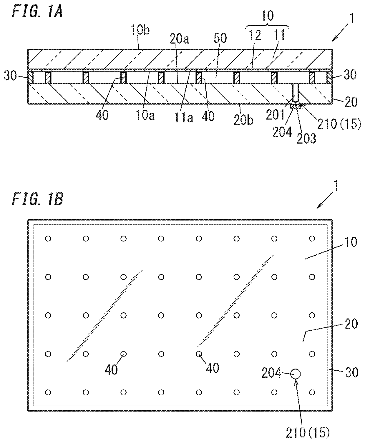
[0021]FIGS. 1A and 1B illustrate a glass panel unit 1 (referred to as a “vacuum glass panel” when the glass panel unit has a vacuum therein) of a first embodiment. FIG. 1A is a cross-sectional view, and FIG. 1B is a plan view. Note that FIGS. 1A and 1B schematically illustrate the glass panel unit, and the dimensions of respective portions thereof are not necessarily to scale and may be different from actual ones. In particular, in FIG. 1A, the thickness of the glass panel unit is illustrated to be larger than the actual one to facilitate the reader's understanding. In addition, in FIGS. 1A and 1B, the spacers are also illustrated in a larger size than actual ones.

[0022]The glass panel unit 1 is basically transparent. Thus, components (such as a frame member 30 and spacers 40) in the glass panel unit 1 are visible. FIG. 1B illustrates such visible internal components. More specifically, FIG. 1B illustrates the glass panel unit 1 seen from a first glass pane 10 thereof.

[0023]The glas...

second embodiment

[0078]FIGS. 6A and 6B show a glass panel unit (a glass panel unit 1A) of a second embodiment. FIG. 6A is a sectional view, and FIG. 6B is a plan view. FIGS. 6A and 6B schematically illustrate the glass panel unit, and similarly to FIGS. 1A and 1B, the dimensions of respective portions thereof are not necessarily to scale and may be different from actual ones

[0079]The glass panel unit 1A of the second embodiment is different from that of the first embodiment in that the exhaust port mark 210 is not provided. Other components of the second embodiment may be the same as those of the first embodiment. When the exhaust port mark 210 is not provided, the appearance of the glass panel unit 1A is improved. Moreover, when the exhaust port mark 210 is not provided, breakage due to the exhaust port mark 210 is suppressed and the durability of the glass panel unit 1A can be improved. Note that in the second embodiment, if an identification structure is provided, the identification structure may...

third embodiment

[0106]FIG. 9 shows a glass panel unit of a third embodiment. FIG. 9 is a sectional view. FIG. 9 schematically shows the glass panel unit, and similarly to FIGS. 1A and 1B, the dimensions of respective portions thereof are not necessarily to scale and may be different from actual ones. Note that a plan view of a glass panel unit 1B corresponds to FIG. 1B and can be understood from FIG. 1B.

[0107]The glass panel unit 1B of the third embodiment includes the glass panel unit 1 of the first embodiment therein. The glass panel unit 1 of the first embodiment is as described above.

[0108]The glass panel unit 1B of the third embodiment includes a third glass pane 60 in addition to a first glass pane 10 and a second glass pane 20. The third glass pane 60 is disposed to face a second surface 10b of the first glass pane 10 or a second surface 20b of the second glass pane 20. One of the first glass pane 10 and the second glass pane 20 is defined as an intermediate glass pane 16. The intermediate g...


PUM

PropertyMeasurementUnit
ultraviolet wavelength rangeaaaaaaaaaa
thicknessaaaaaaaaaa
pressureaaaaaaaaaa

Abstract

An object of the disclosure is to provide a glass panel and a glass window which are configured to stably maintain a depressurized space therein even when their spacers contain a resin. A glass panel unit of an aspect of the disclosure includes: a first glass pane; a second glass pane facing the first glass pane; a frame member which has a frame shape and which the first and second glass panes are bound together through; and spacers containing a resin and disposed between the first and second glass panes. A depressurized space is provided between the first glass pane and the second glass pane. The first and second glass panes are respectively to be exterior and interior panes. The first glass pane has lower ultraviolet transmittance than the second glass pane.

Description

CROSS-REFERENCE OF RELATED APPLICATIONS[0001]This application is the U.S. National Phase under 35 U.S.C. § 371 of International Patent Application No. PCT / JP2017 / 005774, filed on Feb. 16, 2017, which in turn claims the benefit of Japanese Application No. 2016-072498, filed on Mar. 31, 2016, the entire disclosures of which Applications are incorporated by reference herein.TECHNICAL FIELD[0002]The present disclosure relates to a glass panel unit and a glass window including the glass panel unit.BACKGROUND ART[0003]A glass panel including a pair of glass panes (hereinafter referred to as a “glass panel unit”) with a depressurized space between the pair of glass panes has been known in the art. The glass panel unit is also called an “insulated glazing”. The glass panel unit has excellent thermal insulation properties because the depressurized space reduces heat conduction. When a glass panel unit is manufactured, two glass panes to form a pair are bound together with a gap left between ...

Claims


Application Information

Patent Timeline
Patent Type & Authority Patents(United States)
IPC IPC(8): E06B3/66E06B3/667E06B3/677E06B3/663E06B3/67C03C27/10C03C27/06
CPCC03C27/10C03C27/06E06B3/66E06B3/663E06B3/6775E06B3/667E06B3/66304E06B3/6612E06B3/67E06B3/6715Y02A30/249Y02B80/22
Inventor ABEURIU, EIICHIHASEGAWA, KAZUYANONAKA, MASATAKAISHIBASHI, TASUKU
Owner PANASONIC INTELLECTUAL PROPERTY MANAGEMENT CO LTD
Why Eureka
Try Eureka