

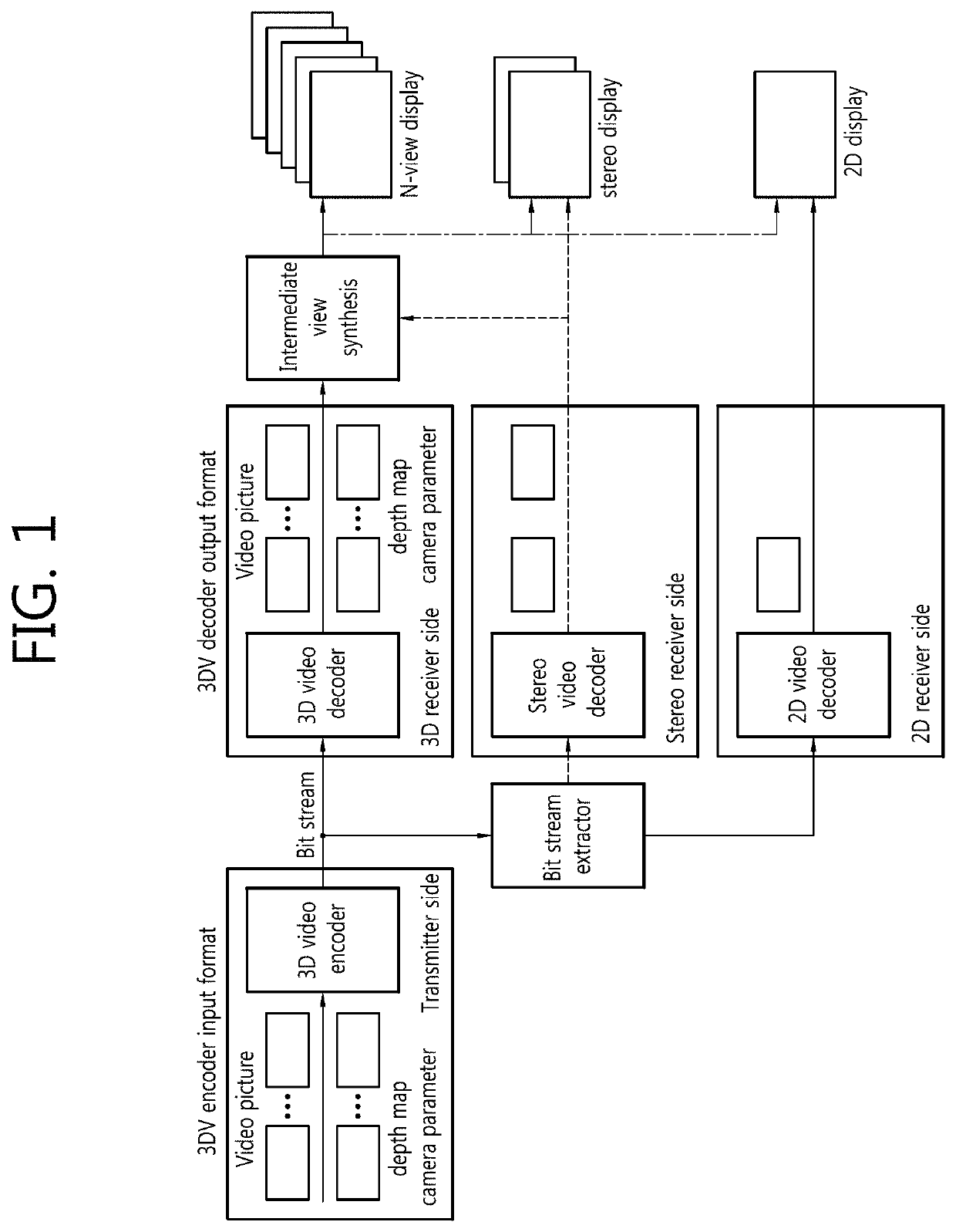
Method and device for inducing motion information between temporal points of sub prediction unit
a technology of motion information and sub-prediction unit, applied in the field of apparatus and methods of encoding/decoding 3d images, can solve the problem that existing image encoding/decoding processes cannot exhibit sufficient encoding/decoding efficiency, and achieve the effect of removing data dependency in deriving motion information, reducing image encoding/decoding efficiency, and increasing image encoding/decoding efficiency
- Summary
- Abstract
- Description
- Claims
- Application Information
AI Technical Summary
Benefits of technology
Problems solved by technology
Method used
Image

Examples
embodiment 1
[0265]FIG. 22 is a flowchart schematically illustrating a method of deriving motion information on a sub prediction unit of a current block using a reference block, according to an embodiment of the present invention.
[0266]In embodiment 1, motion information on a sub prediction unit of a current block (current sub unit) is derived based on motion information for the center position of a reference block. Embodiment 1 may be performed in an encoder and decoder or a predicting unit or inter prediction module of the encoder and decoder. For ease of description herein, the inter prediction module 2100 of FIG. 21 performs the operation of embodiment 1.
[0267]Referring to FIG. 22, the inter prediction module 2100 may derive the center position of the reference block (S2200). The center position of the reference block may be derived from Equation 10 below. Here, the reference block may be a block present at the same position as the current block in the reference picture, and the reference bl...
embodiment 2
[0305]FIG. 23 is a flowchart schematically illustrating a method of deriving motion information on a sub prediction unit of a current block, according to another embodiment of the present invention. In the example illustrated in FIG. 23, motion information on a sub prediction unit of a current block may be derived using a sub prediction unit present at a position of a reference block.
[0306]In embodiment 2, the motion information on the sub prediction unit of the current block may be derived based on the motion information on the sub prediction unit covering the center of the reference block.
[0307]The example shown in FIG. 23 may be performed in an encoder and decoder or a predicting unit of the encoder and decoder or the inter prediction module 2100 shown in FIG. 21. Here, for ease of description, the inter prediction module 2100 performs each step as shown in FIG. 23.
[0308]Referring to FIG. 23, the inter prediction module 2100 may derive the position of the sub prediction unit posi...
embodiment 3
[0341]FIG. 25 is a flowchart illustrating a method of deriving motion information on a sub prediction unit of a current block using a motion information value according to another embodiment of the present invention.
[0342]Referring to FIG. 25, embodiment 4 provides a method of setting default motion information and deriving motion information on a current sub prediction unit from the default motion information in case motion information is impossible to derive from a sub prediction unit of a reference block. Here, the default motion information may mean a zero vector. A specific method of deriving motion information according to embodiment 3 is described below.
[0343]The inter prediction module 2100 may store the default motion information in a storage space (S2500). A specific process of storing motion information by the inter prediction module 2100 has been described above.
[0344]Subsequently, the inter prediction module 2100 may derive motion information on the current sub predicti...
PUM
 Abstract
Description
Claims
Application Information