Flow transition technology

a technology of flow transition and flow direction, applied in computer aided design, geomodelling, instruments, etc., can solve the problems of complex nse, unsatisfactory simulating fluid flow, and simplified nse, so as to maintain acceptable engineering accuracy and improve performance.

Active Publication Date: 2020-06-30
DASSAULT SYSTEMES SIMULIA CORP
View PDF2 Cites 0 Cited by
  • Summary
  • Abstract
  • Description
  • Claims
  • Application Information

AI Technical Summary

Benefits of technology

[0040]The invention described herein is an algorithmic approach to model the flow of fluids through regions characterized by different types of flow as a function of time. The uniqueness of this invention and the value it brings is the concept of automatically switching back and forth between different types of NSE as needed during a numerical simulation in order to improve performance as compared to a full NSE solution while at the same time maintaining acceptable engineering accuracy.

Problems solved by technology

It is difficult to define the actual hydraulic fracture geometry from this data alone.
However, because the analytical model and the empirical approaches cannot handle fractures of arbitrary shape and orientations, a fully 3D hydraulic fracture numerical simulator is vital to the petroleum industry.
In their general form, the NSE are complex, computationally expensive to solve, and typically require sophisticated software tools to generate accurate solutions.
These existing simulation techniques thus rely upon one version of the simplified NSE, which is not ideal for simulating the flow of fluid in a variable environment.

Method used


Image

  • Flow transition technology
  • Flow transition technology
  • Flow transition technology

Examples


Embodiment Construction

[0061]A description of example embodiments of the invention follows.

[0062]The teachings of all patents, published applications, and references cited herein are incorporated by reference in their entirety.

[0063]The targeted use-cases for this invention are engineering scenarios where the appropriate and most efficient version in a given region of the NSE changes over time. In order to give some context two representative applications are described herein below.

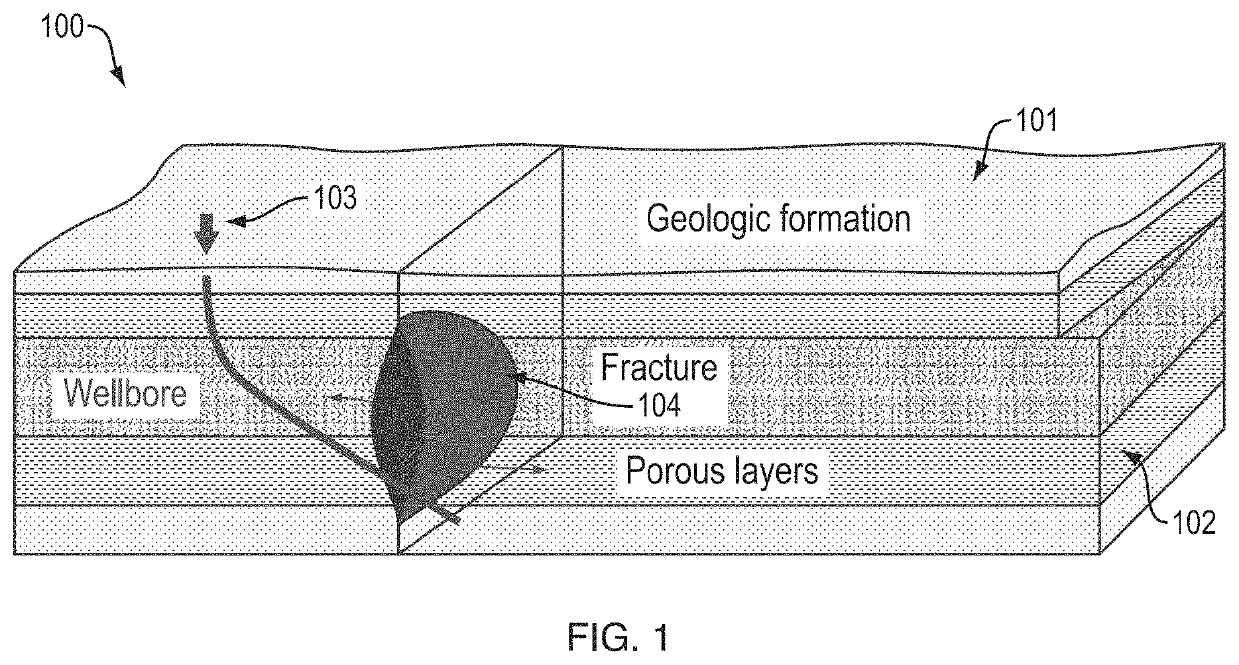
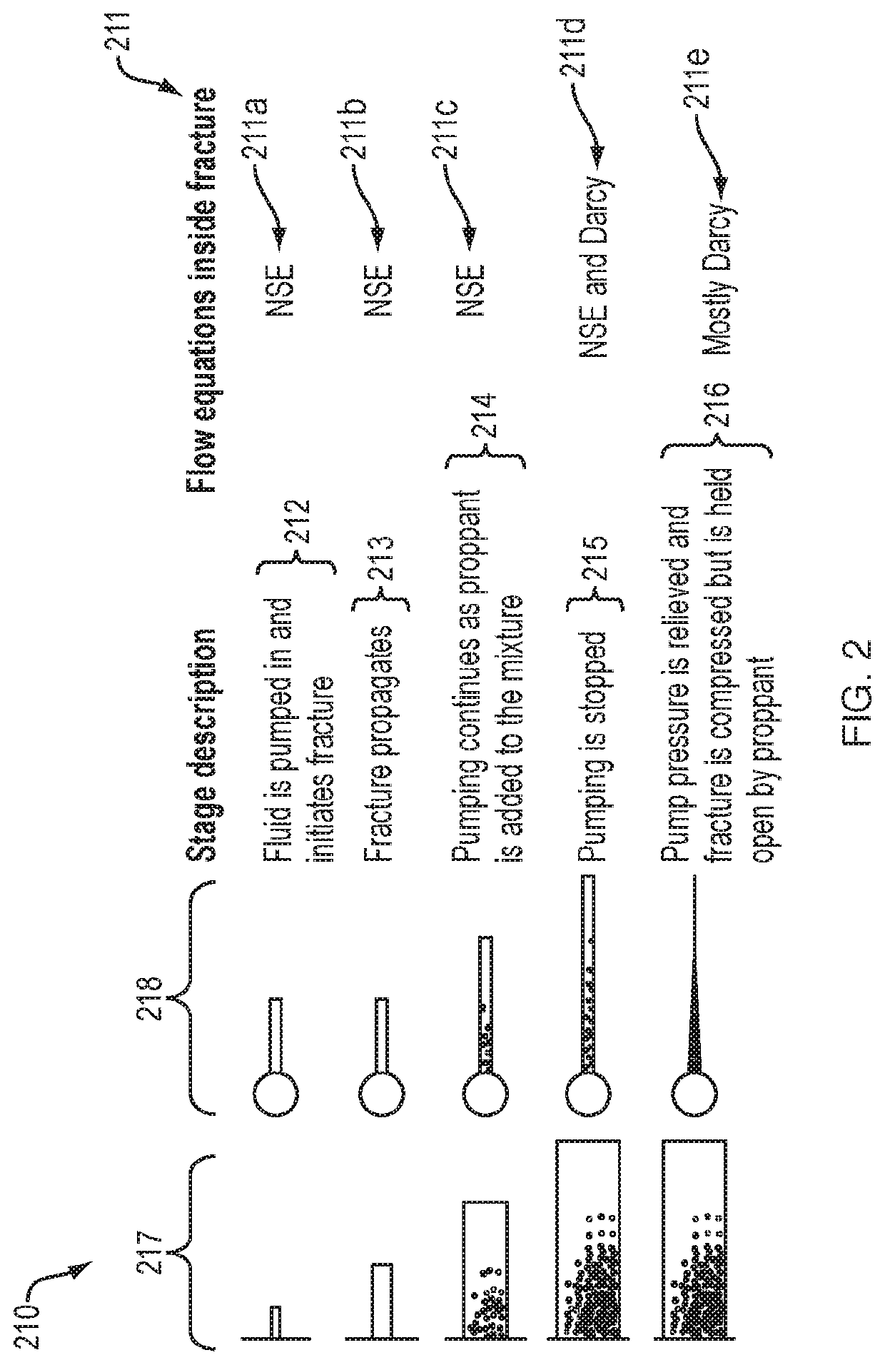
[0064]One field of application for this invention is numerical simulation of hydraulic fracturing, i.e. fracking. Fracking is the process of inducing fracture in rock using fluids pumped in at high pressure. There are a number of common workflows used by the oil and gas industry which rely on fracking. In these workflows, the fracturing of the rock is achieved by pumping fracturing fluid into the target formation (area from which materials are being extracted) with pressure high enough to overcome both the confining hydrostatic...


PUM


Abstract

Embodiments provide methods and systems for modeling the flow of fluid in variable physical and geological environments using dynamically determined Navier-Stokes equations (NSE), such as Darcy Flow and Poiseuille flow.

Description

RELATED APPLICATIONS[0001]This application claims the benefit of U.S. Provisional Application No. 62 / 098,608, filed on Dec. 31, 2015. The entire teachings of the above application(s) are incorporated herein by reference.COMMON OWNERSHIP UNDER JOINT RESEARCH AGREEMENT 35 U.S.C. 102(c)[0002]The subject matter disclosed in this application was developed, and the claimed invention was made by, or on behalf of, one or more parties to a Joint Development Agreement that was in effect on or before the effective filing date of the claimed invention. The parties to the Joint Research Agreement are as follows Dassault Systemes Simulia Corp. and ExxonMobil Upstream Research Company.BACKGROUND OF THE INVENTION[0003]The invention generally relates to the field of computer programs and systems, and to the field of computer aided design (CAD), computer-aided engineering (CAE), modeling, and simulation. Specifically, the invention described herein relates to modeling / simulating the flow of fluids.[0...

Claims


Application Information

Patent Timeline
Patent Type & Authority Patents(United States)
IPC IPC(8): G06F30/00
CPCG06F30/00G01V99/005
Inventor WANG, HONGWUZIELONKA, MATIASXIA, LIN
Owner DASSAULT SYSTEMES SIMULIA CORP
Why Eureka
Try Eureka