Battery monitor control system

a control system and battery monitor technology, applied in the direction of resistance/reactance/impedence, instruments, transportation and packaging, etc., can solve the problems of uninterrupted power, ripple current through the string, catastrophic failure of the string, etc., and achieve the effect of accurate measurement of the unit impedan

Active Publication Date: 2020-07-07
BTECH INC
View PDF15 Cites 1 Cited by
  • Summary
  • Abstract
  • Description
  • Claims
  • Application Information

AI Technical Summary

Benefits of technology

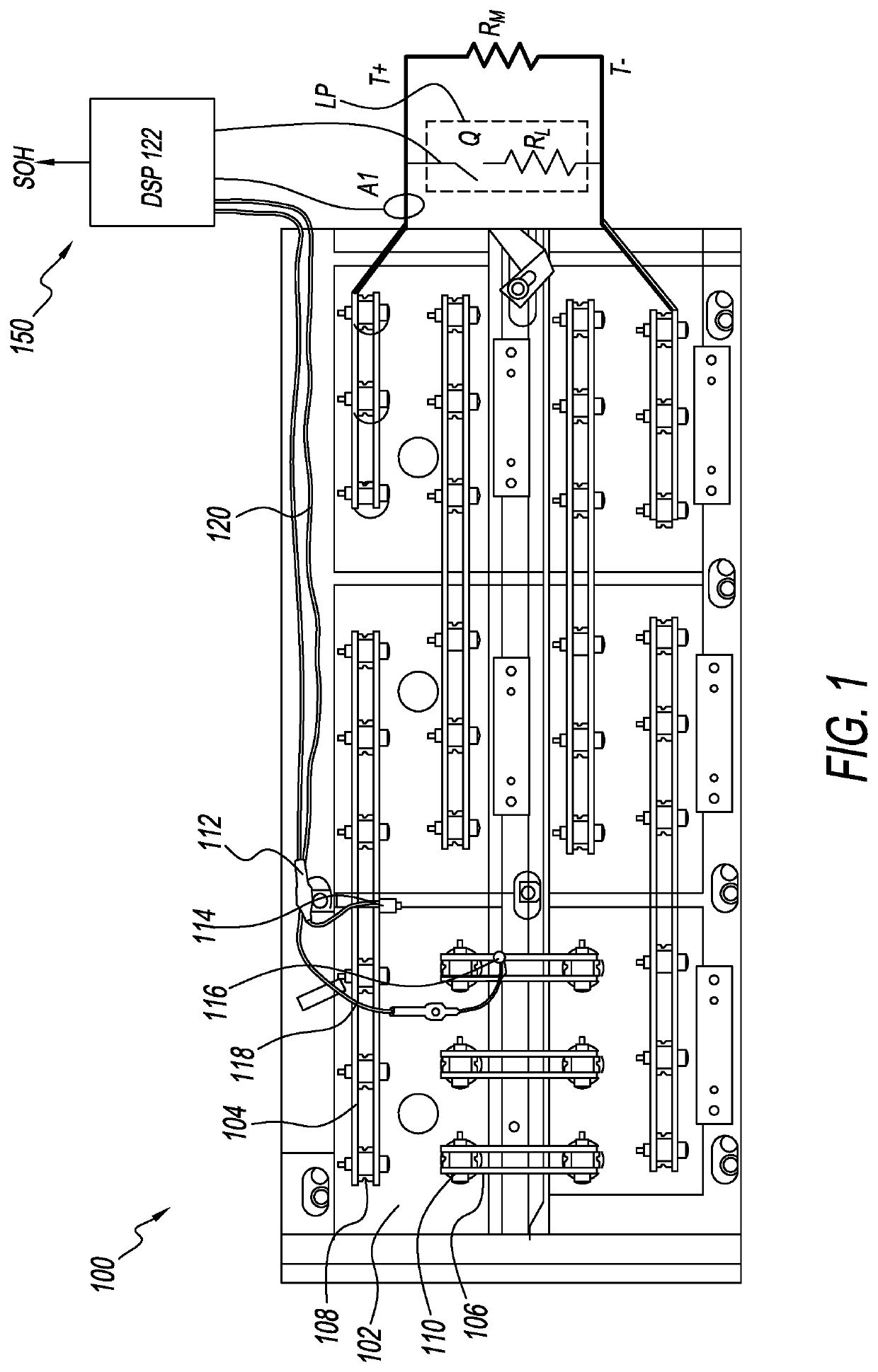
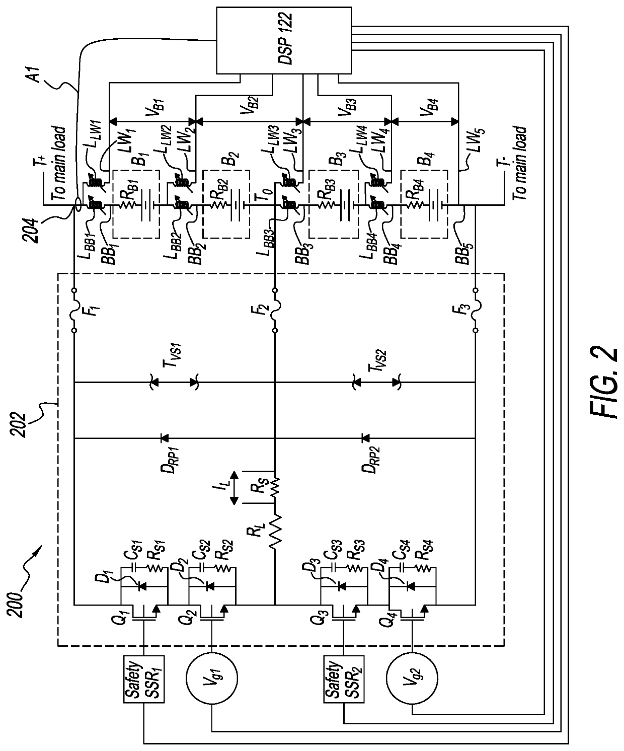
[0011]The impedance in a given unit can be measured by periodically varying a load in parallel to the main load. This can be achieved by opening and closing a switch Q in series with a load resistor RL. This causes a ripple current through the string. The ripple current may be measured by a current sensor A1. Any current sensing technology may be used. The switch and / or load resistor may be mounted on a load plate LP. The load plate can help dissipate heat generated by the switch and / or load resistor. The load plate may be made of a sheet of high conductivity material, such as aluminum or an aluminum alloy. Cooling fins and / or liquid cooling may be supplied to the load plate. A fan may be provided to dissipate heat from the cooling fins.
[0016]The resistive portion of the unit impedance may also include the resistive portion of the busbar between the attachment points of the lead wires. This allows the system to alarm if a busbar is broken or improperly installed. It does not impact the ability of the system to track changes in unit impedance over time since, absent a break or improper installation, the impedance of the busbar may remain constant over time.
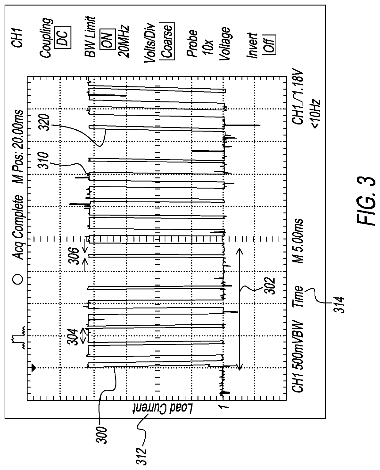
[0017]In a first embodiment, the switch Q is turned on and off at a reference frequency, such as about 50 Hz, to generate the ripple current. The DSP can filter out all higher and lower frequency components of the voltage and current signals to get an impedance measurement at the reference frequency. 50 Hz is a suitable reference frequency since it is high enough to filter out the capacitive portion of the internal impedance of a typical unit and low enough so that changes in busbar impedance due to eddy currents is low. It is also offset from the 60 Hz frequency of line voltage in the United States so that inductive pickup of line voltage can be filtered out. In other jurisdictions, such as Europe, where line voltage is regulated to 50 Hz, the reference frequency can be offset to another value, such as 60 Hz. Reference frequencies in the range of 40 Hz to 70 Hz may be suitable.

Problems solved by technology

If electricity from the utility is lost, then the battery strings discharge through the main load to provide uninterrupted power.
If any individual unit in a string fails, that can cause other units to fail and potentially lead to catastrophic failure of the string, especially under discharge.
This causes a ripple current through the string.

Method used


Image

  • Battery monitor control system
  • Battery monitor control system
  • Battery monitor control system

Examples


Embodiment Construction

[0024]The detailed description describes non-limiting exemplary embodiments. Any individual features may be combined with other features as required by different applications for at least the benefits described herein.

[0025]Both numbers (e.g. 100) letter (e.g. Q) and letters with subscripts (e.g. RL) are used herein to label elements of the figures.

[0026]As used herein, the term “about” means plus or minus 10% of a given value unless specifically indicated otherwise.

[0027]Examples provided in the singular imply examples in the plural and vice versa.

[0028]A portion of the disclosure of this patent document contains material to which a claim for copyright is made. The copyright owner has no objection to the facsimile reproduction by anyone of the patent document or the patent disclosure, as it appears in the Patent and Trademark Office patent file or records, but reserves all other copyright rights whatsoever.

[0029]As used herein, a “computer-based system” comprises an input device fo...


PUM


Abstract

A battery monitor control system has a load plate, two or more lead wires connected to two or more busbars in a string of batteries, and a digital signal processor. The load plate has one or more primary switches connected to two or more terminals of the batteries in the string of batteries. The load plate also has a load resistor and a current sensor. The primary switches are turned on and off to produce a ripple current in the string of batteries. The digital signal processor determines the real portion of the complex impedance of at least one of the batteries by analyzing the voltage and current waveform of the ripple current. The primary switches may be turned on and off with a sine wave modulation.

Description

TECHNICAL FIELD[0001]The inventions described herein are in the field of battery monitors.BACKGROUND ART[0002]There is a long felt need to accurately measure the internal impedance of a battery unit. As used herein, a “battery unit” or “unit” is the smallest part of a battery that can be connected to a battery monitor. A battery unit may be, but is not limited to, one or more of:[0003]Cell: An individual electrochemical device composed of two electrodes of dissimilar metals (active materials) and an electrolyte. When the electrodes are immersed in an electrolyte, the cell will produce a voltage differential between the electrodes. When connected to electrodes, the cell will produce a current through an external circuit.[0004]Jar: One or more cells in a battery string manufactured and contained in a single container.[0005]Monobloc: Two or more separate but electrically connected cells each of which is designed to house an assembly of electrodes, electrolyte, terminals or interconnect...

Claims


Application Information

Patent Timeline
Patent Type & Authority Patents(United States)
IPC IPC(8): H02J7/02G01R27/08G01R31/392G01R31/389H02J7/00
CPCG01R31/392G01R31/389G01R27/08H02J7/0016Y02E60/10
Inventor POTEMPA, EDWARD M.BAUM, JR., ALLAN J.
Owner BTECH INC
Why Eureka
Try Eureka