

Power system for a marine vehicle, comprising a propulsion unit, a rudder bearing and fittings
a technology for marine vehicles and power systems, applied in bearings, roller bearings, shafts, etc., can solve the problems of rudder bearing position, drive unit mounting, and occurrence of leverage effect, so as to facilitate the delivery, mounting and dismounting of the power system on a marine vehicle, and reduce the effect of leverage
- Summary
- Abstract
- Description
- Claims
- Application Information
AI Technical Summary
Benefits of technology
Problems solved by technology
Method used
Image

Examples
Embodiment Construction
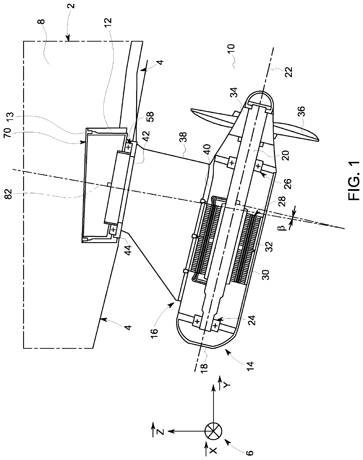
[0031]With reference to FIG. 1, it represents the stern 4 of a ship 2. A system of vectors 6 is defined relative to the ship 2. The system 6 consists of three orthogonal vectors, and. The vector is perpendicular to the plane of FIG. 1 and led by the pitch axis of the ship 2, while ship 2 is arranged according to a normal operating plane. A normal operation plane is the one containing longitudinal and transverse directions of the ship 2, while the latter moves on a calm sea and under normal loading conditions. The vector is horizontal relative to the plane of FIG. 1 and oriented according to the roll axis of the ship 2, while the ship 2 is arranged according to a normal operating plane. The vector is vertical relative to FIG. 1 and oriented according to the yaw axis of the ship 2, while the ship 2 is arranged according to a normal operating plane. Also as defined by FIG. 1, compared with the hull element 4, an inner part 8 and an outer part 10.
[0032]The hull element 4 has a bore lead...
PUM
 Abstract
Description
Claims
Application Information