Thermal transfer sheet

a technology of thermal transfer sheet and transfer sheet, which is applied in the field of thermal transfer sheet, can solve the problems of inability failure to form a thermal transferable image, etc., and achieve the effect of satisfactory transferability

Active Publication Date: 2020-08-11
DAI NIPPON PRINTING CO LTD
View PDF29 Cites 0 Cited by
  • Summary
  • Abstract
  • Description
  • Claims
  • Application Information

AI Technical Summary

Benefits of technology

[0014]According to the thermal transfer sheet of the present invention, it is possible to make the transferability satisfactory when the transfer layer including a receiving layer is transferred over a wide energy range.

Problems solved by technology

This thermal transfer sheet, in which the receiving layer is not located on the outermost surface of the thermal transfer sheet in advance of transferring the transfer layer, fails to form a thermally transferable image.
This is because it is not possible to form a thermally transferable image on the receiving layer included in the transfer layer in the case where the layer located on the outermost surface is not the receiving layer after transferring when the transfer layer is transferred onto the transfer receiving article.

Method used


Image

  • Thermal transfer sheet
  • Thermal transfer sheet
  • Thermal transfer sheet

Examples


example 1

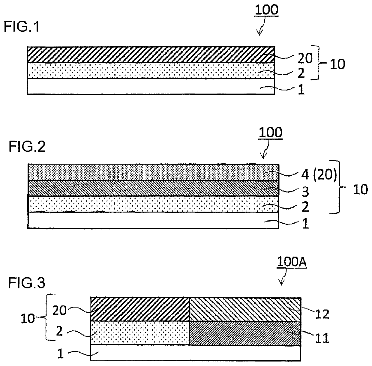
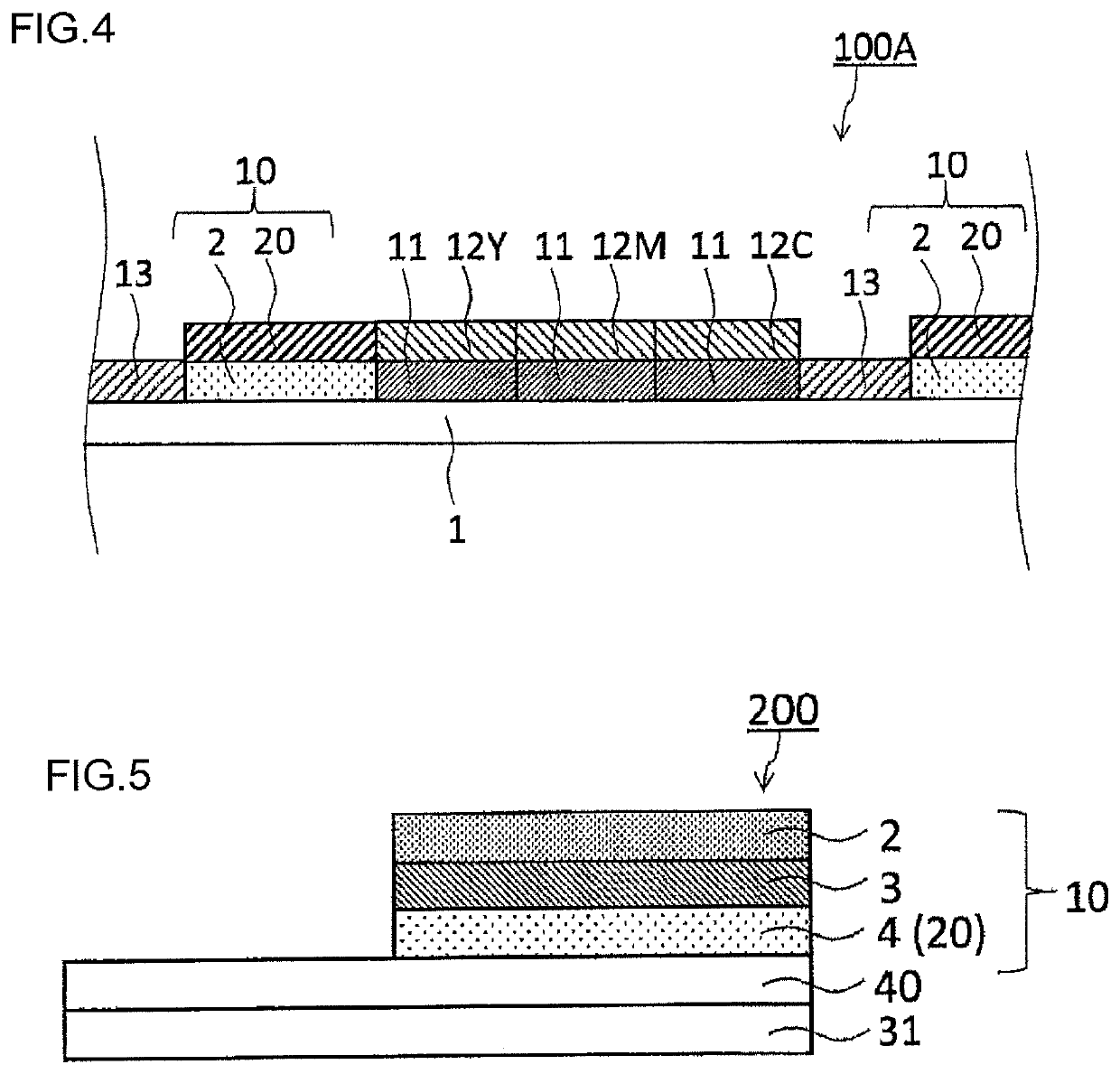
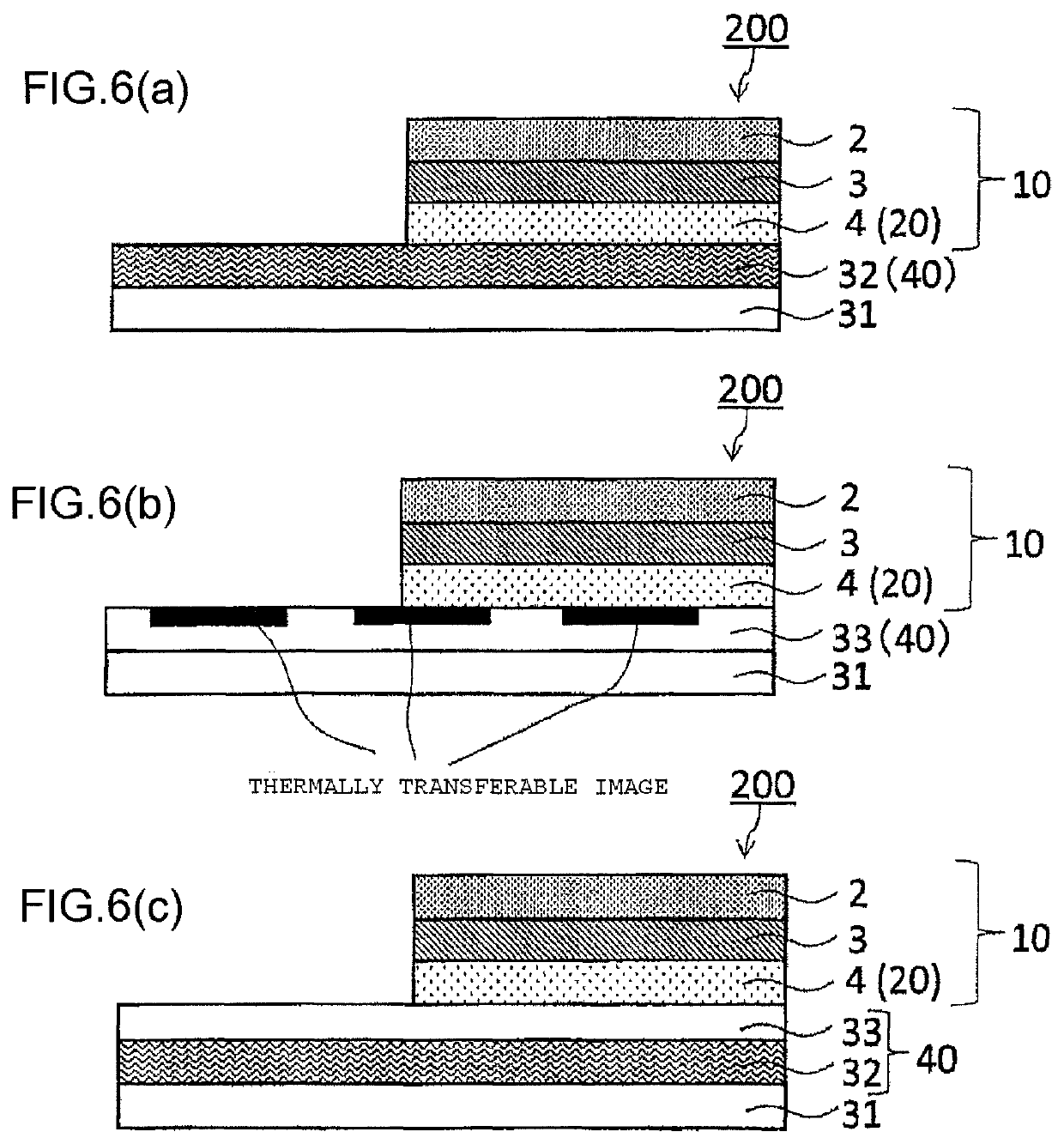
[0105]Using a polyethylene terephthalate film of 5 μm in thickness as a substrate, the substrate was coated with a coating liquid for the back face layer having the following composition so as to reach 1.0 g / m2 in a dried state, and a back face layer was formed. Then, the surface of the substrate opposite to the surface on which the back face layer was provided was coated with a coating liquid 1 for the first receiving layer having the following composition so as to reach 1.0 g / m2 in a dried state, and a first receiving layer was formed. Then, the first receiving layer was coated with a coating liquid for the first intermediate layer having the following composition so as to reach 0.15 g / m2 in a dried state, and a first intermediate layer was formed. Then, the first intermediate layer was coated with a coating liquid for the masking layer having the following composition so as to reach 2.0 g / m2 in a dried state, and a masking layer was formed. Thus, the thermal transfer sheet of Exa...

example 2

[0114]The thermal transfer sheet of Example 2 was obtained totally in the same manner as in Example 1 except that the first receiving layer was formed by using a coating liquid 2 for the first receiving layer in which 1.0 part of cellulose acetate butyrate resin (CAB381-0.5, Eastman Chemical Company) (Mn: 30000) in the coating liquid 1 for the first receiving layer was replaced by 1.0 part of cellulose acetate butyrate resin (Mn: 20000) (CAB381-0.1, Eastman Chemical Company), instead of the coating liquid 1 for the first receiving layer.

example 3

[0115]The thermal transfer sheet of Example 3 was obtained totally in the same manner as in Example 1 except that the first receiving layer was formed by using a coating liquid 3 for the first receiving layer in which 1.0 part of cellulose acetate butyrate resin (CAB381-0.5, Eastman Chemical Company) (Mn: 30000) in the coating liquid 1 for the first receiving layer was replaced by 1.0 part of cellulose acetate butyrate resin (Mn: 40000) (CAB381-2, Eastman Chemical Company), instead of the coating liquid 1 for the first receiving layer.


PUM

PropertyMeasurementUnit
thicknessaaaaaaaaaa
thicknessaaaaaaaaaa
thicknessaaaaaaaaaa

Abstract

There is provided a thermal transfer sheet having satisfactory transferability when a transfer layer is transferred on a transfer receiving article over a wide energy range.A thermal transfer sheet 100 for obtaining a thermal transfer image-receiving sheet includes a substrate 1 and a transfer layer 10 provided on the substrate, wherein the transfer layer 10 has a layered structure in which two or more layers are layered, the transfer layer 10 includes at least a receiving layer 2, the layer located nearest to the substrate 1 of the layers constituting the transfer layer 10 is the receiving layer 2, and the receiving layer 2 contains a cellulosic resin.

Description

BACKGROUND OF THE INVENTION1. Field of the Invention[0001]The present invention relates to a thermal transfer sheet, specifically relates to a thermal transfer sheet used for obtaining a thermal transfer image-receiving sheet.2. Description of Related Art[0002]As a device for forming a printed product on a transfer receiving article without restriction, an intermediate transfer medium in which a transfer layer including a protective layer and a receiving layer are layered on a substrate in this order from the substrate side has been used (for example, Patent Literature 1). According to this intermediate transfer medium, a printed product where a thermally transferable image has been formed on a transfer receiving article can be obtained by forming the thermally transferable image on a receiving layer located on the outermost surface of the intermediate transfer medium by means of a thermal transfer sheet having a colorant layer, and then transferring the receiving layer on which the...

Claims


Application Information

Patent Timeline
Patent Type & Authority Patents(United States)
IPC IPC(8): B41M5/382B41M5/44B41M5/52
CPCB41M5/5236B41M5/44B41M5/38214B41M2205/38B41M2205/30B41M2205/32B41M5/382B41M5/42
Inventor YONEYAMA, YASUSHIYAMASHITA, HIROYUKI
Owner DAI NIPPON PRINTING CO LTD
Why Eureka
Try Eureka