
Hoisting winch assembly

a technology of hoisting winch and assembly, which is applied in the direction of hoisting equipment, cranes, transportation and packaging, etc., can solve the problems of high assembly cost, no longer being maintained, and difficult to mount so as to facilitate the mounting of the hoisting winch assembly and avoid costly and expensive mechanical treatment of the surface disposed far apar

Active Publication Date: 2020-08-11
LIEBHERR COMPONENTS BIBERACH GMBH
View PDF25 Cites 0 Cited by
  • Summary
  • Abstract
  • Description
  • Claims
  • Application Information

AI Technical Summary

Benefits of technology

The invention proposes a hoisting winch assembly with separate power transmission for each motor to the drums. This leads to a more compact and lightweight construction, as less power needs to be transmitted. High hoisting powers can also be achieved, as each motor drives only one drum. Compared to conventional assemblies, the brake assembly is smaller and can handle higher loads. A modular construction makes it easy to mount and test the assembly. Overall, the technical effects of the invention are a more efficient and compact hoisting winch assembly.

Problems solved by technology

Such drive of the hoisting winches by a common motor ensures the synchronous run of the two drums, but only is used primarily for limited performance ranges, as a common motor otherwise cannot provide the performances required for both hoisting winches or would be dimensioned so large that the specified mounting dimensions and the specified axial spacing of the drums, which only provides a limited gap between the opposite end faces of the drums, might no longer be maintained.
The motors arranged beside the drums however in turn lead to arrangement problems or constraints during installation, as the motors are to be arranged in a particular sector, so as not to collide with the cables running off.
On the other hand, the assembly of the hoisting winch system is very expensive.

Method used


Image

  • Hoisting winch assembly
  • Hoisting winch assembly
  • Hoisting winch assembly

Examples


Embodiment Construction

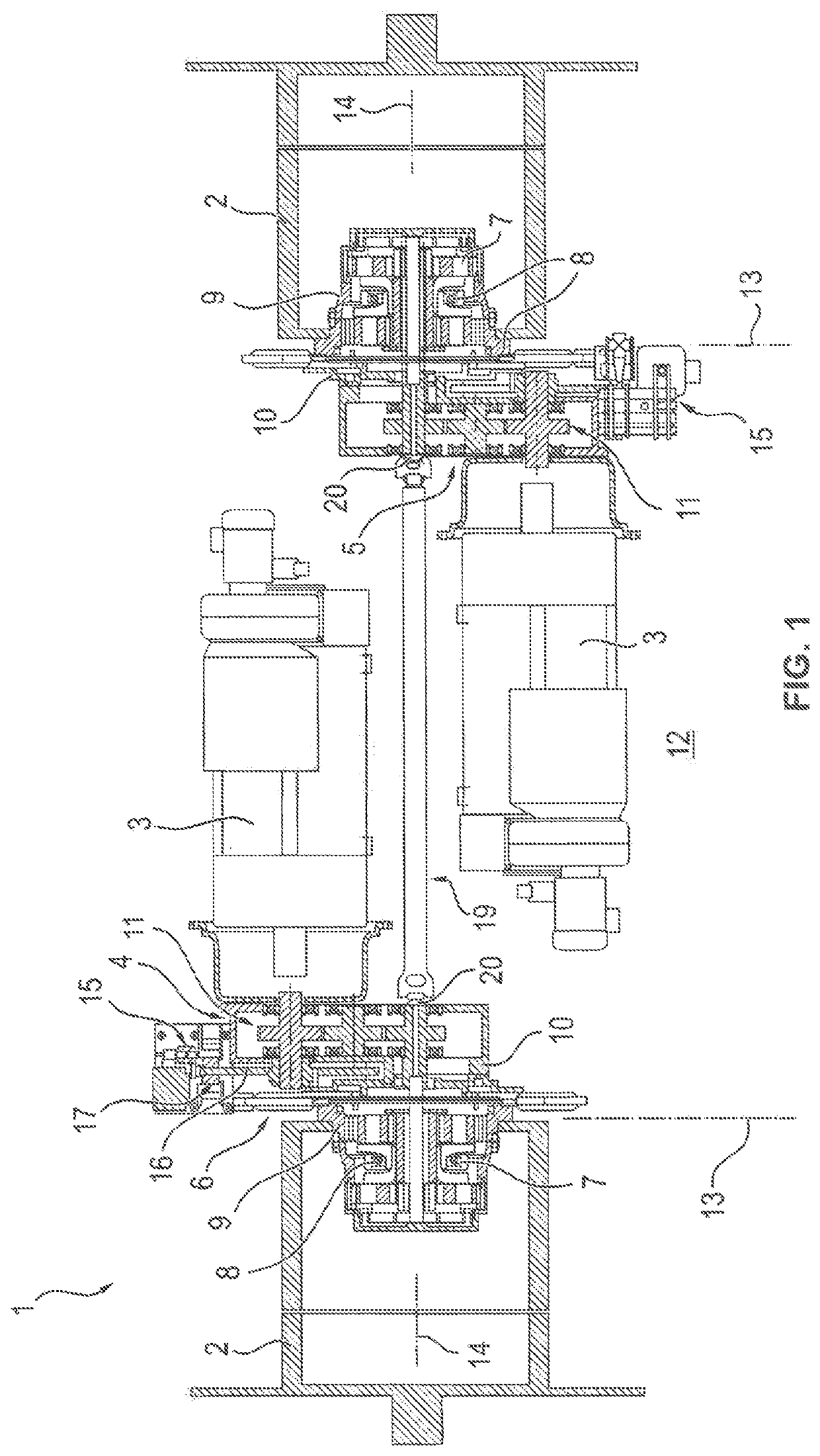
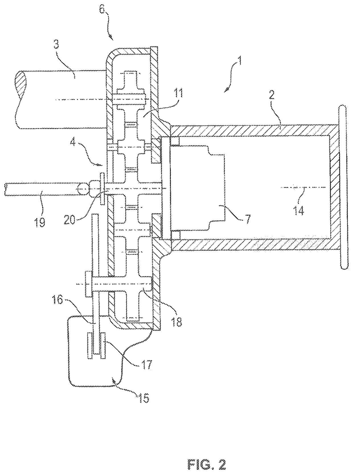
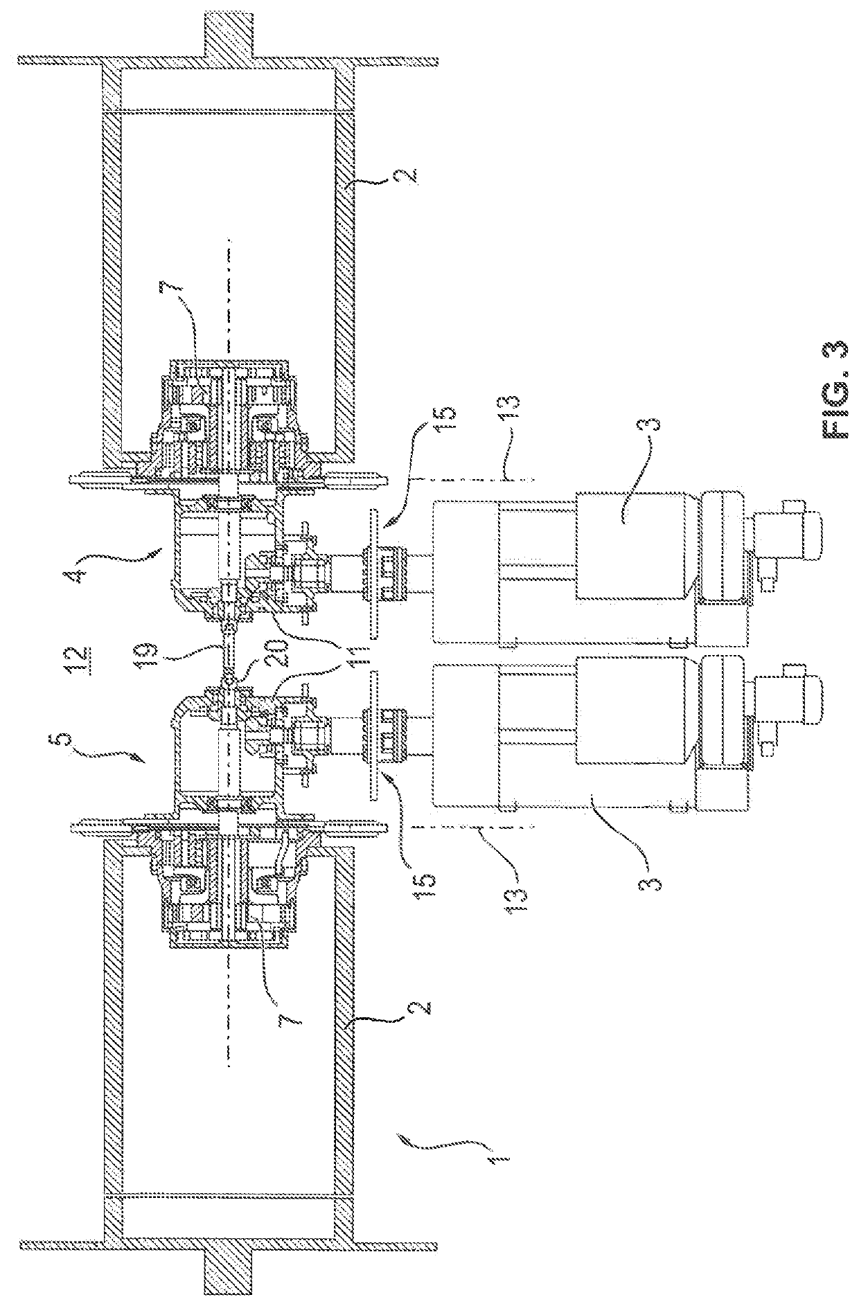
[0029]As shown in the Figures, the hoisting winch assembly 1 comprises two axially parallel drums 2 spaced from each other, which as regards their basic structure can be configured in a manner customary per se, in particular can comprise a grooved drum body with flanged wheels. On end-face edge portions the drums 2 also can comprise non-grooved cylinder portions which form a reserve, if a longer cable is to be drawn up. In a manner known per se, two cables can run off from each drum 2, as can be the case for example in gantry or container cranes, in order to be able to stably lift and lower the hoisting harness for picking up containers.

[0030]As shown in the Figures, the drums 2 in particular can be arranged coaxially to each other.

[0031]Each of the drums 2 here is driven by a motor 3 which is in drive connection with only one drum each by a separate gear train 4 or 5 of a transmission assembly 6.

[0032]As shown in FIGS. 1 and 3, each of said gear trains 4 and 5 can comprise a drum t...


PUM


Abstract

The present invention relates to a hoisting winch assembly comprising at least two preferably axially parallel drums spaced from each other axially, which can be driven in synchronism with each other by two motors via a transmission assembly. The invention furthermore relates to a crane, in particular a gantry and / or container crane, with such hoisting winch assembly. According to the invention, the transmission assembly has at least two separate gear trains, so that each motor is in drive connection with one drum each via a separate gear train. As compared to a common transmission to which both motors are connected, the separate gear trains can be configured significantly lighter and smaller, as no longer the power of both motors added up, but only the power of one motor must be transmitted. Nevertheless, high hoisting powers can be provided on the whole, as each motor must drive only one drum.

Description

CROSS-REFERENCE TO RELATED APPLICATIONS[0001]This application is a continuation of International Application No. PCT / EP2016 / 001060, filed Jun. 22, 2016, which claims priority to German Utility Model No. 20 2015 004 788.2, filed Jul. 3, 2015, and German Utility Model No. 20 2015 006 083.8, filed Aug. 28, 2015, all of which are incorporated by reference herein in their entireties.BACKGROUND[0002]1) Technical Field[0003]The present invention relates to a hoisting winch assembly comprising at least two preferably axially parallel drums spaced from each other axially, which can be driven in synchronism with each other by two motors via a transmission assembly. The invention furthermore relates to a crane, in particular a gantry and / or container crane, with such hoisting winch assembly.[0004]2) Description of the Related Art[0005]The document DE 10 2009 050 584 A1 shows a container crane whose hoisting gear includes two axially parallel drums spaced from each other axially, i.e. in the di...

Claims


Application Information

Patent Timeline
Patent Type & Authority Patents(United States)
IPC IPC(8): B66D1/26B66D1/12B66D1/14B66C19/00
CPCB66D1/14B66D1/12B66C19/007B66D1/26
Inventor PAAL, MARTINKREYSSIG, STEVENBULLING, JOHANNES
Owner LIEBHERR COMPONENTS BIBERACH GMBH
Learn More