Electrosurgical device

a surgical device and electrode technology, applied in the field of electrosurgical devices, can solve problems such as tissue damage, and achieve the effect of preventing tissue damage during surgery

Active Publication Date: 2020-08-18
GYRUS MEDICAL LTD
View PDF31 Cites 386 Cited by
  • Summary
  • Abstract
  • Description
  • Claims
  • Application Information

AI Technical Summary

Benefits of technology

[0005]Embodiments of the present invention provide an improved surgical instrument having an end effector mounted on the end of an elongate shaft extending from a handle. The end-effector is capable of several different operations, including grasping, cutting, and sealing and / or coagulating tissue, and one of the operations is controlled by a drive handle mechanism as described herein. The drive handle mechanism comprises an actuator, a drive shaft and a spring assembly for transferring movement of the actuator to the drive shaft, which in turn controls the end effector. The drive handle mechanism is arranged so as to limit the amount of force transferred from the drive handle mechanism to the end effector, thus preventing damage to the tissue being operated on. Specifically, as the actuator is operated by the user, the spring assembly is arranged to transfer the movement of the actuator to the drive shaft and the end effector. At the same time, the spring assembly is arranged to compress in order to absorb some of the force applied by the user, particularly in the case where tissue is clamped between the end effector. Such a configuration thereby prevents the tissue being unintentionally damaged by the end effector by too much clamping force being applied thereto.

Problems solved by technology

Therefore, when tissue is clamped between the jaws, it is important to limit the load exerted by the drive handle as this can lead to the tissue being damaged.

Method used


Image

  • Electrosurgical device
  • Electrosurgical device
  • Electrosurgical device

Examples


Embodiment Construction

[0074]An embodiment of the invention will now be described. A brief overview of the whole embodiment will first be given, followed by detailed descriptions of particular aspects thereof.

[0075]1. Overview of the Configuration of the Instrument

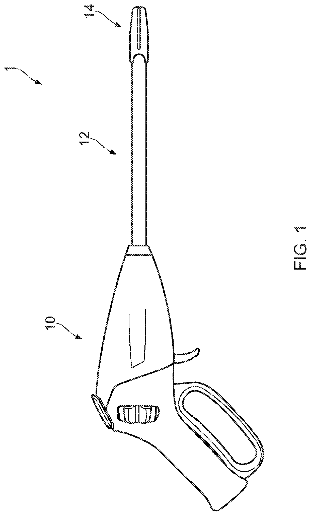
[0076]FIG. 1 illustrates an electrosurgical instrument 1 according to an example of the present invention. The instrument 1 includes a proximal handle portion 10, an outer shaft 12 extending in a distal direction away from the proximal handle portion, and a distal end effector assembly 14 mounted on a distal end of the outer shaft. The end effector assembly 14 may by way of example be a set of opposed jaws arranged to open and close, and comprising one or more electrodes arranged on or as the inner opposed surfaces of the jaws and which in use have connections to receive an electrosurgical radio frequency (RF) signal for the sealing or coagulation of tissue. The jaws are further provided with a slot or other opening within the inner opposed surf...


PUM

PropertyMeasurementUnit
surface areaaaaaaaaaaa
angular rotationaaaaaaaaaa

Abstract

An improved surgical instrument having an end effector mounted on the end of an elongate shaft extending from a handle. The end-effector has different operations, including grasping, cutting, and sealing and / or coagulating tissue, and one of the operations is controlled by a drive handle mechanism. The drive handle mechanism includes an actuator, a drive shaft and a spring assembly for transferring movement of the actuator to the drive shaft, which in turn controls the end effector. The drive handle mechanism limits the amount of force transferred from the drive handle mechanism to the end effector, preventing damage to the tissue. As the actuator is operated, the spring assembly transfers the movement of the actuator to the drive shaft and the end effector. At the same time, the spring assembly compresses to absorb some of the force applied. Such configuration prevents the tissue being unintentionally damaged by the end effector.

Description

[0001]This nonprovisional application claims the benefit of priority to GB 1600546.4, filed Jan. 12, 2016, and GB 1600591.0, filed Jan. 12, 2016. The disclosure of the prior applications is hereby incorporated by reference herein in its entirety.TECHNICAL FIELD[0002]Embodiments of the present invention described herein relate to an electrosurgical device, and in particular an electrosurgical forceps device wherein a mechanical blade provides a tissue cutting action in combination with electrosurgical electrodes providing a tissue coagulation or sealing effect.BACKGROUND TO THE INVENTION AND PRIOR ART[0003]Electrosurgical instruments provide advantages over traditional surgical instruments in that they can be used for coagulation and tissue sealing purposes. One such prior art arrangement is known from US2015 / 223870A1, which describes an endoscopic bipolar forceps including a housing and a shaft, the shaft having an electrosurgical end effector assembly at a distal end thereof, which...

Claims


Application Information

Patent Timeline
Patent Type & Authority Patents(United States)
IPC IPC(8): A61B17/29A61B18/14A61B18/00A61B17/00A61B90/00
CPCA61B18/1445A61B17/29A61B17/2909A61B2017/00367A61B2017/00371A61B2017/292A61B2017/293A61B2017/2913A61B2017/2929A61B2017/2945A61B2017/2946A61B2018/0063A61B2018/00083A61B2018/0091A61B2018/0094A61B2018/00142A61B2018/00178A61B2018/00184A61B2018/00202A61B2018/00589A61B2018/00601A61B2018/00607A61B2018/00952A61B2018/1455A61B2090/032A61B2090/035A61B18/12A61B18/1442A61B18/1482A61B18/14A61B2018/00059A61B2018/00351A61B2018/00702A61B2017/00017A61B2018/1467A61B2018/1452A61B2018/00916A61B17/295A61B2017/2919A61B2017/2912A61B2017/2903A61B2017/32113A61B2017/2948A61B2017/2932A61B18/00
Inventor NAGTEGAAL, MARNO
Owner GYRUS MEDICAL LTD
Why Eureka
Try Eureka