Method for processing a workpiece

Active Publication Date: 2020-08-18
KONRAD GMBH
View PDF17 Cites 0 Cited by
  • Summary
  • Abstract
  • Description
  • Claims
  • Application Information

AI Technical Summary

Benefits of technology

[0008]Described by way of example is a case from the production of an automotive part. For example, a luggage space lid is to be produced in a corresponding press. Production takes place between two dies. During production, it is possible for an object of some kind, for example a screw, to accidentally come between these two dies. This screw then presses into one of the dies, leaving a flaw.
[0009]In one process step according to the present invention, an image is now recorded of the to-be-processed region or the flaw in the workpiece. This can be a normal image or, as in the preferred exemplary embodiment, a 3D image.
[0010]This image appears on a display element, for example a screen, an iPad or even 3D glasses. The screen or iPad, or the 3D glasses, are able to move and need not be located in the same space as the workpiece that is to be processed. This has the considerable advantage that the user need not be in the same space as the dangerous laser.
[0011]In order to identify the position, in a preferred exemplary embodiment lines are stuck to the workpiece paral

Problems solved by technology

During production, it is possible for an object of some kind, f

Method used


Image

  • Method for processing a workpiece
  • Method for processing a workpiece

Examples


Example

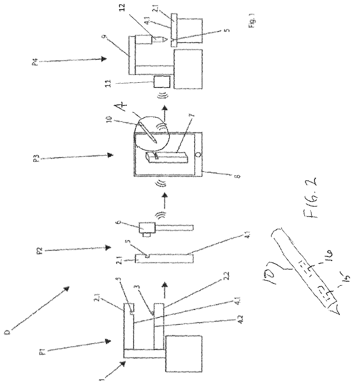
[0026]Other advantages, features and details of the invention can be found in the following description of preferred exemplary embodiments and in the drawing, which shows, in FIG. 1, a schematic illustration of an apparatus according to the invention for processing a workpiece. This figure represents the schematic illustration D of the process according to the invention, with the process steps P1-P4.

[0027]The preferred exemplary embodiment shows, as first process step P1, a press 1, for example from the automotive industry. This tool has dies 2.1 and 2.2. If an object 3, for example a screw, were now to fall between the dies 2.1 and 2.2, and the dies 2.1 and 2.2 close, at least one surface 4.1 and / or 4.2 of at least one die 2.1 and / or 2.2 would suffer substantial damage, resulting in a flaw 5.

[0028]In order to repair this flaw 5, in a second process step P2 a camera 6, preferably a 3D camera, is moved to the flaw 5. This records a 3D image 7 of the damaged location.

[0029]In order to...


PUM


Abstract

In a method for processing a workpiece (2) using a tool (9), in particular for repairing a surface (4) using a laser, the tool (9) being piloted by a control element (10), the tool (9) is to be controlled via a position of the control element (10) and a pressure which is applied either to the control element (10) or by the control element (10).

Description

BACKGROUND OF THE INVENTION[0001]The invention relates to a method for processing a workpiece using a tool, in particular for repairing a surface using a laser, the tool being piloted by a control element.[0002]Methods of this kind for processing a workpiece using a tool, for example a laser, are known in a great many forms and embodiments. In that context, lasers can be used in many forms for the processing of workpieces, such as for cutting workpieces, hardening workpiece surfaces, or also for connecting workpieces by welding. In this processing method, it is often necessary to observe the workpiece region that is to be processed using an observation device, such as a microscope, in order to be able to guide with sufficient precision over the workpiece a laser beam that is used for processing. If the welding takes the form of deposition welding, in which a welding wire must be brought over the point that is to be welded, the use of such an observation device is practically indispe...

Claims


Application Information

Patent Timeline
IPC IPC(8): B23K26/03B25J9/16B23K26/34B23K26/342B23P6/00B23K101/00B23K101/18
CPCB23K26/032B23K26/342B23K26/34B25J9/1697G05B2219/45104B23P6/00B23K2101/18B23K2101/006B23K26/042
Inventor KONRAD, MICHAEL
Owner KONRAD GMBH
Why Eureka
Try Eureka