Lamella-shaped targets for x-ray generation

a technology of x-ray generation and lasers, applied in the field of x-ray targets, can solve the problems of limited resolution, excessive heating, and limited imaging resolution, and achieve the effects of improving throughput, maintaining resolution, and improving the design of x-ray targets

Active Publication Date: 2020-08-18
FEI CO
View PDF14 Cites 1 Cited by
  • Summary
  • Abstract
  • Description
  • Claims
  • Application Information

AI Technical Summary

Benefits of technology

[0031]A system for producing an x-ray image of a sample uses a lamella-shaped target to improve the usual tradeoff between imaging resolution and image acquisition time. An electron beam is directed along a first axis onto a first surface of a lamella-shaped target. The impact of the electrons in the beam onto the lamella-shaped target generates x-rays from within an interaction volume within the lamella-shaped target, and a portion of the x-rays are emitted towards an x-ray detector. A sample is positioned along a second axis between the lamella-shaped target and the x-ray detector. An x-ray image is acquired by collecting the x-rays which are not absorbed by the sample.

Problems solved by technology

However, the impact of the electron beam with the target can cause excessive heating and even melting of the target, thus electron beam currents may be limited to less than 1-2 μA for beam energies up to 60 keV.
While some x-ray generating systems use focusing optics to focus the generated x-rays, other systems do not use focusing optics.
However, imaging resolutions were limited by the spreading of the electron beam within the target material, since the electron dissipation volume also corresponds to the virtual source size, and thus resolutions were limited.
However, due to the small cross-sectional area of the posts, thermal conductivity is much lower than for a bulk target, and thus excessive heating presents a limit to the allowable electron beam energy which may be deposited into the target before melting may occur (even for tungsten targets).
Hence, both the commonly-used bulk targets, and the more recently-developed post targets present difficulties for optimizing the resolution and throughput of a SEM-based nanotomography system.
A disadvantage of a bulk target is that the virtual source size is determined by the penetration volume (142 in FIG. 1C and 162 in FIG. 1D).

Method used


Image

  • Lamella-shaped targets for x-ray generation
  • Lamella-shaped targets for x-ray generation
  • Lamella-shaped targets for x-ray generation

Examples


first embodiment

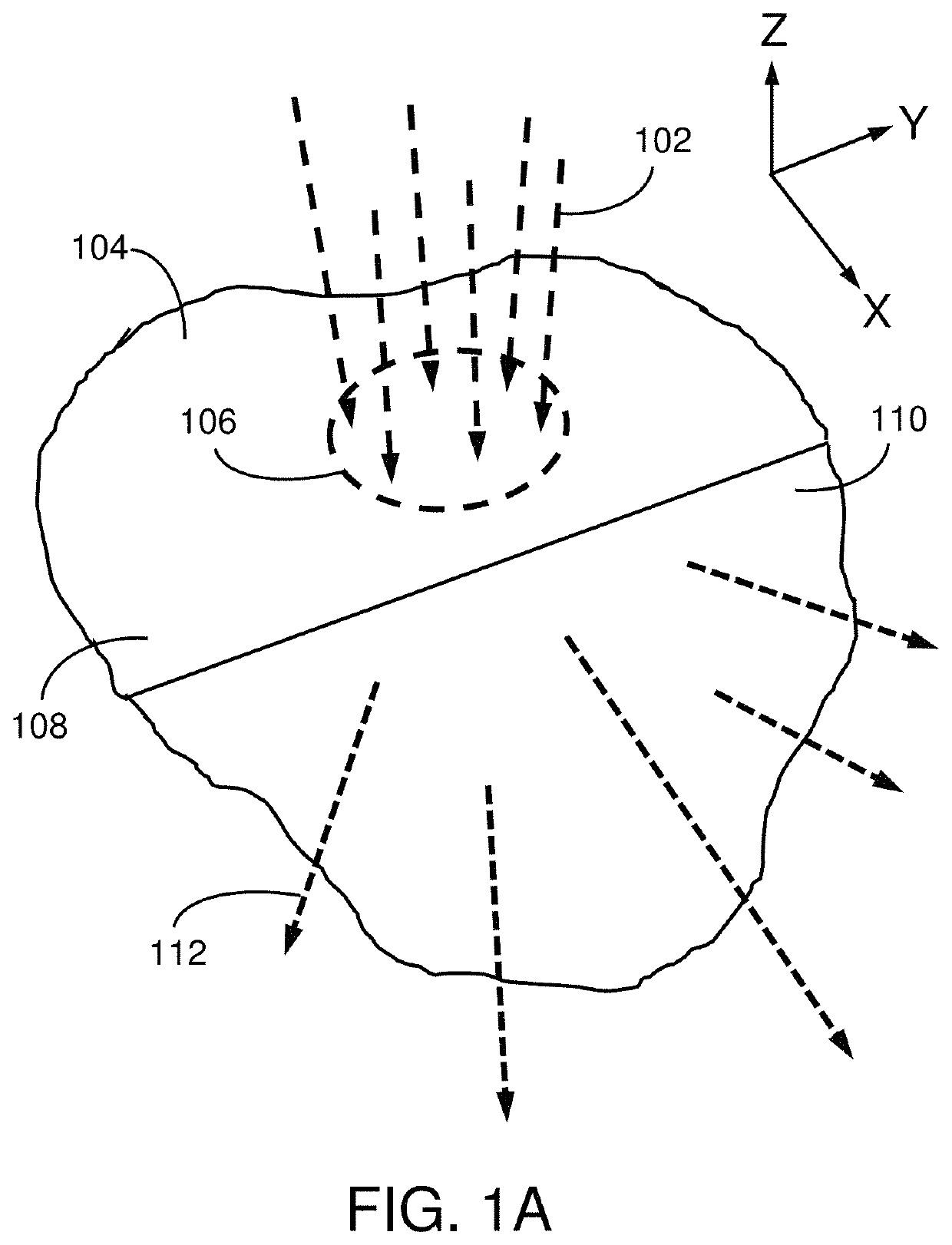
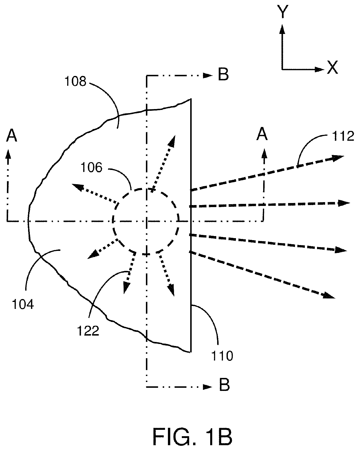
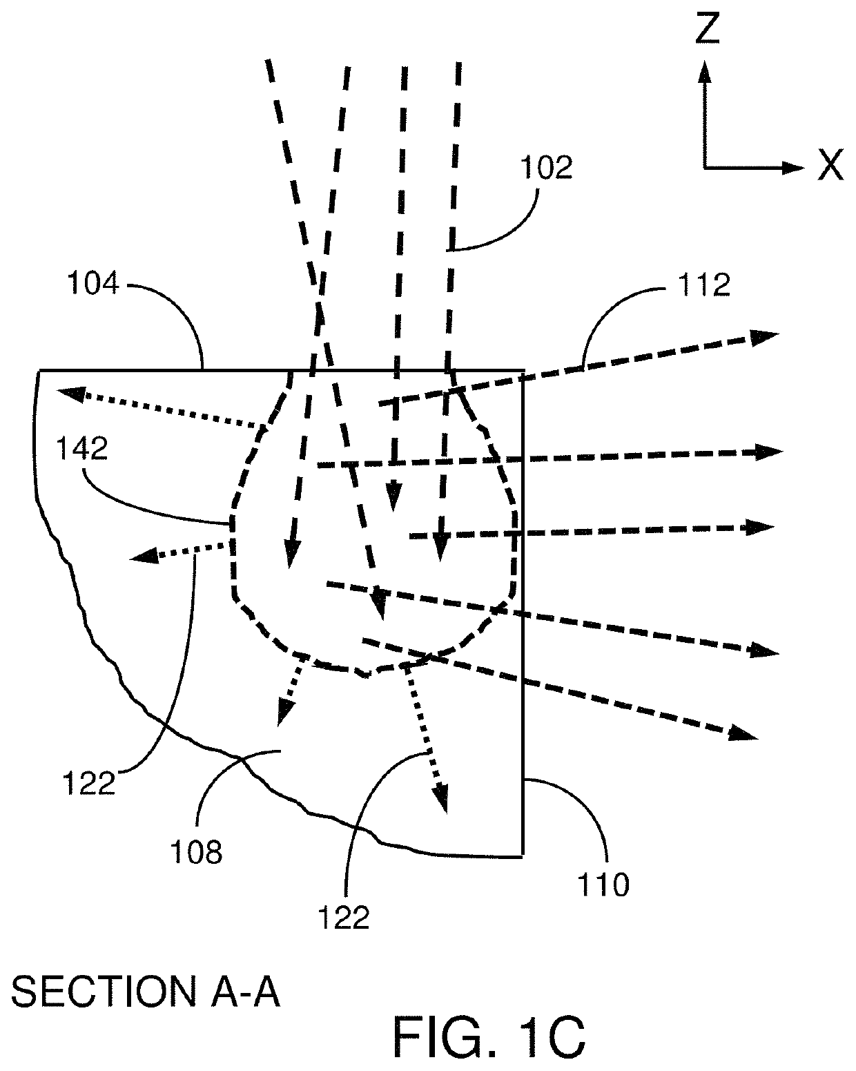
[0073]A first embodiment, which is a method for producing an x-ray image of a sample, the method comprising directing a beam of electrons having landing energies of less than 2,000 eV along a first axis onto a first surface of a lamella-shaped target, the impact of the electrons in the beam onto the lamella-shaped target generating x-rays from within an interaction volume within the lamella-shaped target, wherein a portion of the x-rays are emitted towards an x-ray detector; positioning a sample along a second axis between the lamella-shaped target and the x-ray detector; and acquiring an x-ray image by collecting the x-rays which are not absorbed by the sample using the x-ray detector, wherein the lamella-shaped target has a height in a direction along the first axis, a length in a direction along the second axis, and a width along a third axis that is different from the first and second axes; the height and the length are at least twice the width; and the electron beam interaction...

ninth embodiment

[0081]A ninth embodiment, which is a method for producing an x-ray image of a sample, the method comprising directing an electron beam along a first axis onto a first surface of a lamella-shaped target, the impact of the electrons in the beam onto the lamella-shaped target generating x-rays, wherein a portion of the x-rays are emitted towards an x-ray detector; positioning a sample along a second axis between the lamella-shaped target and the x-ray detector; and acquiring an x-ray image by collecting the x-rays which are not absorbed by the sample using the x-ray detector, in which the lamella-shaped target has a height in a direction along the first axis, a length in a direction along the second axis, and a width along a third axis that is different from the first and second axes, the height and the length being at least twice the width.

[0082]A tenth embodiment, which is the method of the eighth embodiment, in which the height and the length are at least three times the width.

[0083...


PUM

PropertyMeasurementUnit
widthaaaaaaaaaa
widthaaaaaaaaaa
widthaaaaaaaaaa

Abstract

A method and system are disclosed for producing an x-ray image of a sample using a lamella-shaped target to improve the usual tradeoff between imaging resolution and image acquisition time. A beam of electrons impacts the lamella-shaped target normal to the narrower dimension of the lamella which then determines the virtual source size along that axis. For low-energy x-ray generation, the small electron penetration depth parallel to the wider dimension of the lamella determines the virtual source size along that axis. Conductive cooling of the target is improved over post targets with the same imaging resolution. The lamella-shaped target is long enough to ensure that the electron beam does not impact the support structure which would degrade the imaging resolution. Target materials may be selected from the same metals used for bulk or post targets, including tungsten, molybdenum, titanium, scandium, vanadium, silver, or a refractory metal.

Description

TECHNICAL FIELD OF THE INVENTION[0001]The present invention relates to systems for generating x-rays and, in particular, to x-ray targets designed to increase the resolution and / or throughput of x-ray imaging and tomography systems.BACKGROUND OF THE INVENTION[0002]An x-ray tomography system can provide information of the internal structure of a sample without having to destroy or cross-section the sample. The X-rays are passed through the sample and detected by an x-ray detector to obtain an absorption image from a cross-section of the sample. The x-ray detector acquires a two-dimensional x-ray shadow (absorption-contrast) image. For three-dimensional tomography, the sample and / or x-ray source and detector may be incrementally rotated to enable cross sectional images to be obtained from multiple angles. The set of cross-sectional images obtained in this manner can then be mathematically manipulated to reconstruct a 3D image of the sample.[0003]The term: “SEM-based nanotomography sys...

Claims


Application Information

Patent Timeline
Patent Type & Authority Patents(United States)
IPC IPC(8): G01N23/046G21K7/00H01J35/08
CPCG01N23/046G21K7/00H01J35/08G01N2223/401H01J2235/086G01N2223/419H01J2235/081G01N2223/204
Inventor FILEVICH, JORGE
Owner FEI CO
Why Eureka
Try Eureka