
High-temperature superconducting magnet online monitoring system

A high-temperature superconducting and monitoring system technology, applied in thermometers, measuring devices, measuring heat, etc., can solve the problems of temperature, current and voltage monitoring difficulties, small heat capacity, and aggravating the danger of hot spots.

Inactive Publication Date: 2014-12-10
INST OF ELECTRICAL ENG CHINESE ACAD OF SCI +1
View PDF5 Cites 22 Cited by
  • Summary
  • Abstract
  • Description
  • Claims
  • Application Information

AI Technical Summary

Problems solved by technology

However, the high-temperature superconducting tape, which is the main component of the high-temperature superconducting magnet, is generally in the environment of high voltage and strong magnetic field, so it is difficult to monitor the temperature, current and voltage.
Especially for high-temperature superconducting magnets under conduction cooling conditions, it is not only necessary to monitor them quickly and accurately, but also the monitoring system itself must ensure that external heat cannot be introduced casually, which will aggravate the danger of potential hot spots, because for the second In the first generation of high-temperature superconducting strips, the superconducting layer of the strip itself is very thin, and the volume of the superconducting strip per unit length is small, so the heat capacity is small, and the temperature rises quickly when the timeout is lost. Once the temperature is overheated, it is very easy to burn out, which will cause the entire magnet system quench and burn

Method used


Image

  • High-temperature superconducting magnet online monitoring system
  • High-temperature superconducting magnet online monitoring system
  • High-temperature superconducting magnet online monitoring system

Examples


Embodiment Construction

[0048] The present invention will be described in detail below in conjunction with the accompanying drawings and specific embodiments.

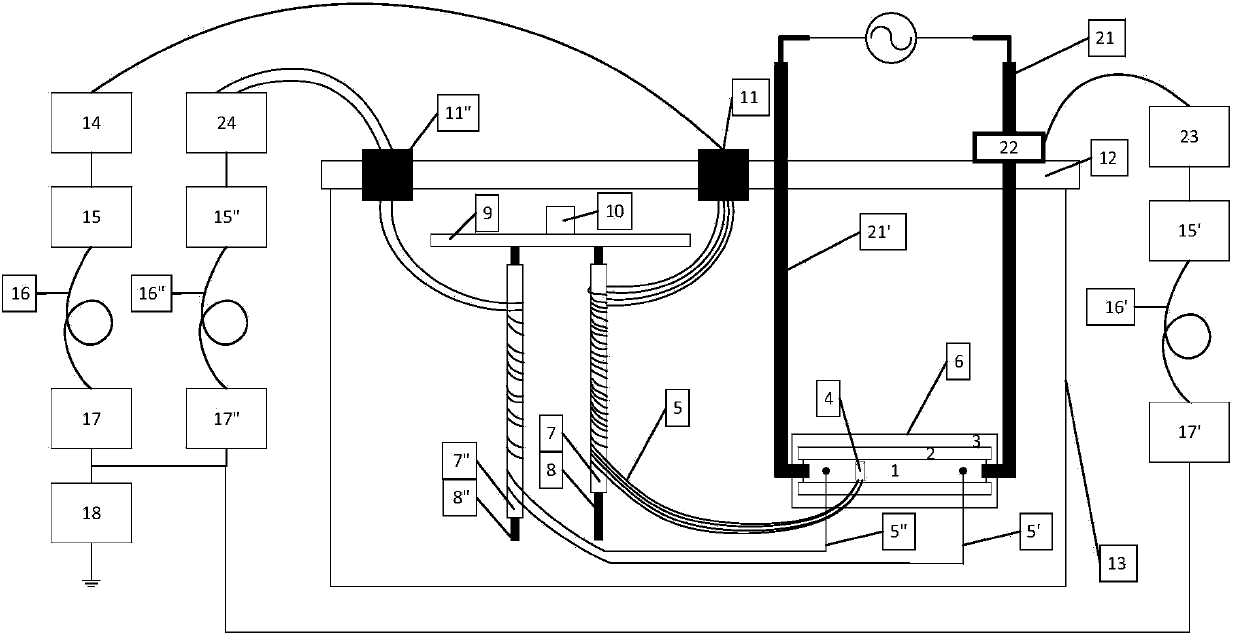
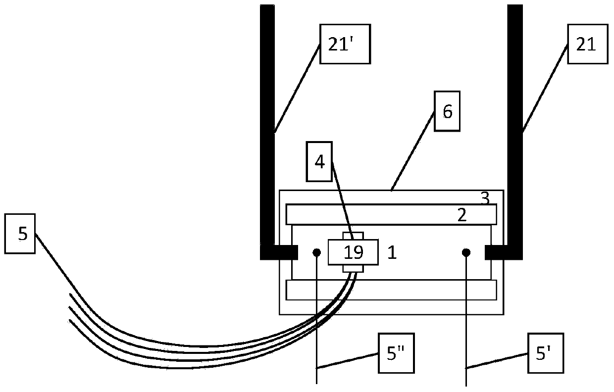
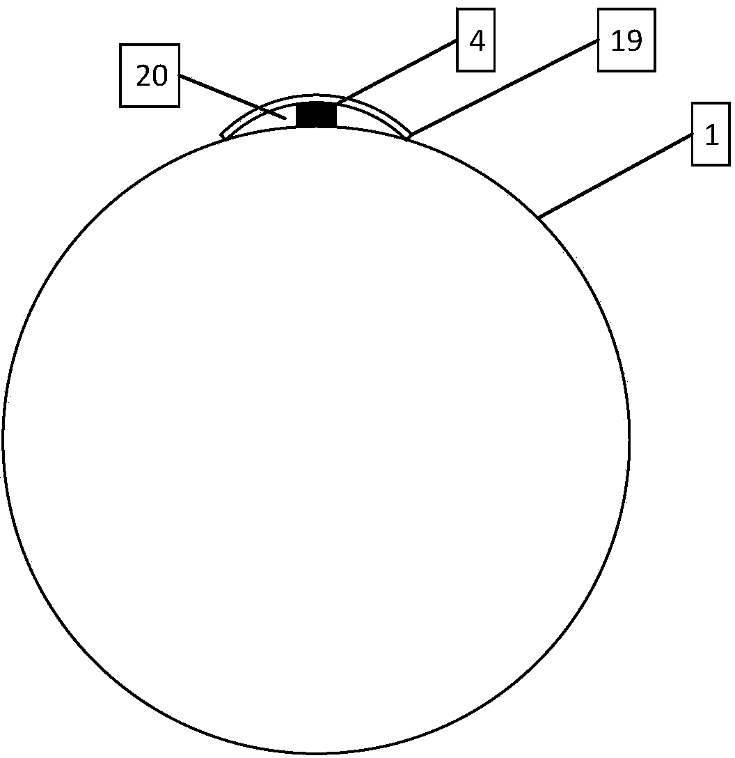
[0049] Figure 1 ~ Figure 3 Shown is the online monitoring system of the high temperature superconducting magnet of the present invention.

[0050] figure 1 Shown, the online monitoring system of the present invention comprises:

[0051] 1) A high-temperature superconducting magnet system 6, which includes: a high-temperature superconducting strip 1, a conduction-cooled superconducting magnet skeleton 2, a first current lead 21 and a second current lead 21'; The superconducting strip 1 is wound on the conduction cooling superconducting magnet skeleton 2; one end of the first current lead 21 and the first end of the high temperature superconducting strip 1 are connected to each other by welding, The other end of the first current lead 21 is connected to the first end of the external power supply; one end of the second current lead 21' is co...


PUM


Abstract

A high-temperature superconducting magnet online monitoring system comprises a high-temperature superconducting magnet system, a conduction cooling refrigeration system, a low-temperature Dewar system, a testing device, a digital voltage meter, a carburizing ceramic temperature sensor, a measuring manganin wire, a heat conduction insulating layer, a temperature transmitter, a fiber converter, a fiber, a compression joint copper sheet and low-temperature high vacuum grease, the cooling refrigeration system comprises a refrigerating machine cold head, a copper cold conduction connecting plate and a copper cold conduction framework, the heat conduction insulating layer coats the copper cold conduction framework, the testing device comprises a computer and a current sensor, the middle of the measuring manganin wire is wound on the heat conduction insulating layer, the carburizing ceramic temperature sensor is directly pressed on the surface of a high-temperature superconducting strip, two ends of the carburizing ceramic temperature sensor are directly fixed on the surface of the high-temperature superconducting strip, gaps among the compression joint copper sheet, the carburizing ceramic temperature sensor and the high-temperature superconducting strip are filled with the low-temperature high vacuum grease for assisting in fixing the carburizing ceramic temperature sensor and conducting heat.

Description

technical field [0001] The invention relates to a monitoring system for a high-temperature superconducting magnet. Background technique [0002] In 1911, Dutch physicist Camerin Onnes discovered superconductors. Superconductors have unique physical properties such as zero resistance, complete diamagnetism and quantum tunneling effect. Since the discovery of superconductors, superconductivity and its applications have been one of the most active frontier research fields in contemporary science and technology. In energy, It has important application value in information, transportation, scientific instruments, medical technology, national defense and major scientific projects. [0003] Superconductivity was first discovered in mercury by Dutch physicist Onnes in 1911. It refers to the phenomenon that the resistance of a superconductor suddenly disappears when the temperature drops to a certain value. This characteristic temperature is defined as the critical transition temp...

Claims


Application Information

Patent Timeline
IPC IPC(8): G01R19/25G01K11/32
Inventor 许熙马韬李侠郭文勇牛帅张京业王玉平戴少涛
Owner INST OF ELECTRICAL ENG CHINESE ACAD OF SCI
Learn More