
Method for protecting a link in an optical network

a technology of optical network and protection technique, applied in the field of communication technology, can solve the problems of inability to finely optimize, subject to strict reliability constraints, and extremely time-consuming

Active Publication Date: 2020-08-18
XIEON NETWORKS SARL
View PDF80 Cites 6 Cited by
  • Summary
  • Abstract
  • Description
  • Claims
  • Application Information

AI Technical Summary

Benefits of technology

The invention is a method for transmitting digital data over a network using a modulation format that allows for a degree of constellation distortion. This means that the positions of constellation points in the constellation diagram may be varied in a predetermined way to improve the protection of priority traffic. The method also includes evaluating the quality of alternative protection links and determining the degree of distortion of the constellation diagram to ensure optimal transmission quality. The use of higher priority traffic and distortion of the constellation diagram can improve network efficiency and allow for faster recovery of high-priority traffic in case of failure. Additionally, the modulation format, distortion degree, and evaluation of alternative protection links can be adaptable based on the quality of the network.

Problems solved by technology

Transport networks are critical telecommunication infrastructures and are therefore subject to strict reliability constraints.
This situation is not uncommon, especially when the backup is shared and hence cannot be finely optimized as the working path.
Unfortunately, both approaches require, besides some signaling overhead, a full reconfiguration of the transponders at the end nodes of the link, which would typically include reprogramming registers of framer and modem devices, tuning analog oscillators and adjusting analog signal levels.
This process is, however, extremely time-consuming and results in practice into severe service interruption which will often not be tolerable for high-priority traffic.
However, this solution comes at a tremendous cost in terms of required overcapacity in the network.
Further, this cost increases with the network size due to the growing number of possible failure scenarios that must be taken into account.
Obviously, also this solution comes at a high price, because it sacrifices throughput during normal operation to guarantee a quick failure response.

Method used


Image

  • Method for protecting a link in an optical network
  • Method for protecting a link in an optical network
  • Method for protecting a link in an optical network

Examples


Embodiment Construction

[0054]For the purposes of promoting an understanding of the principles of the invention, reference will now be made to a preferred embodiment illustrated in the drawings, and specific language will be used to describe the same. It will nevertheless be understood that no limitation of the scope of the invention is thereby intended, such alterations and further modifications in the illustrated apparatus and such further applications of the principles of the invention as illustrated therein being contemplated as would normally occur now or in the future to one skilled in the art to which the invention relates.

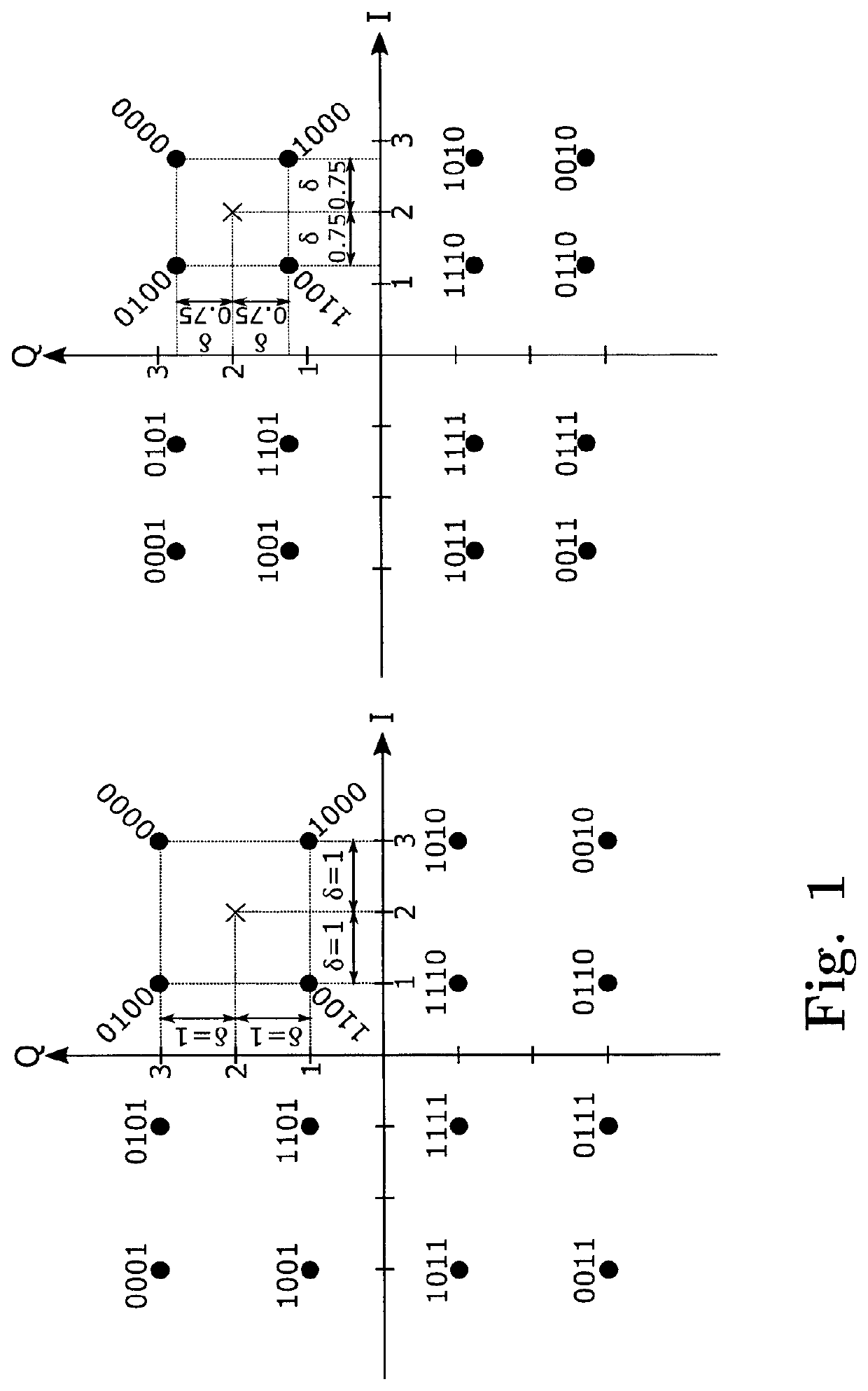
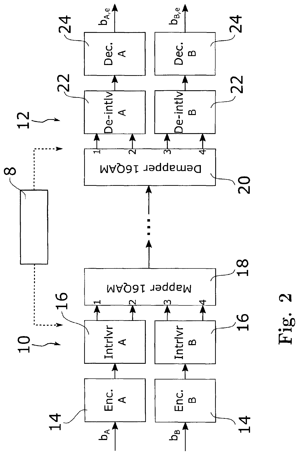
[0055]For the sake of exemplification we give a detailed description of the method of the invention for the important case that the given link or “working path” carries a payload of about 200 Gb / s, shortly referred to as a “200G client”, over a single optical carrier. The modulation format of choice for this application is considered to be DP-16QAM.

[0056]The left side of FIG. 1 sh...


PUM


Abstract

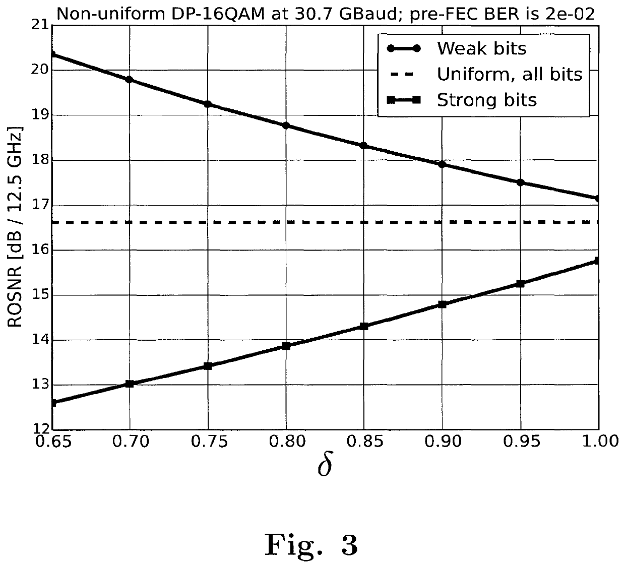
Enclosed herewith is a method for protecting a link in an optical network configured for transmitting digital data employing a predetermined modulation format which comprises a number of symbols in a constellation diagram. A binary address is associated with each symbol. The modulation format allows for a constellation distortion, according to which the relative positions of constellation points in the constellation diagram are varied in a predetermined way by a predetermined degree. The method the steps of: A) partitioning the traffic in two or more priority classes, B) mapping higher priority traffic to predefined bit positions within the binary symbol addresses, C) evaluating the quality of a predetermined protection link, D) determining a degree of distortion such that a desired transmission quality for the transmission of the traffic of the highest priority class or classes via said predetermined protection link and a desired transmission quality for the full traffic via said given link are simultaneously ensured, and E) employing said distorted constellation diagram for transmission of digital data over said given link.

Description

RELATED APPLICATIONS[0001]This application is a 35 U.S.C. 371 national stage filing of International Application No. PCT / EP2017 / 056758, filed on Mar. 22, 2017, which claims priority to European Patent Application No. 16161645.3, Mar. 22, 2016. The entire contents of these applications are incorporated herein by reference in their entirety.FIELD OF THE INVENTION[0002]The present invention is in the field of communication technology. In particular, the present invention relates to a fast protection technique realized in the optical transport layer of a network.BACKGROUND OF THE INVENTION[0003]Optical networks are usually organized in ring or meshed structures consisting of several nodes connected by unidirectional or, more often, bidirectional links. The usage of reconfigurable optical cross-connects introduces the possibility to reroute traffic and reallocate network resources in a dynamic way.[0004]Modern optical transport networks for telecommunications rely upon coherent technolog...

Claims


Application Information

Patent Timeline
Patent Type & Authority Patents(United States)
IPC IPC(8): H04L27/34H04L27/36H04L1/00H04J14/02H04B10/032H04B10/548H04B10/516H04B10/54
CPCH04B10/548H04L27/3405H04B10/541H04L1/007H04L27/367H04L27/3444H04B10/5161H04B10/032
Inventor RAFIQUE, DANISHCALABRO, STEFANO
Owner XIEON NETWORKS SARL
Learn More