Medical examination sight maintaining videoscope

a technology for medical examination and videoscopes, applied in the field of medical examination sight maintaining videoscopes, can solve the problems of not being able to maintain the object to be examined, and certain limitations on the improvement of the insertability and operability of the scope tip-end section with respect to the object, so as to improve the insertability and operability of the scope tip-end section

Active Publication Date: 2020-09-01
MPI INC
View PDF15 Cites 0 Cited by
  • Summary
  • Abstract
  • Description
  • Claims
  • Application Information

AI Technical Summary

Benefits of technology

[0005]An embodiment described herein aims to provide a technique making it possible to image and record an object to be examined and visualize the object on a monitor while maintaining the object to be examined, for example, an aural cavity, oral cavity, nasal cavity or the like within the sight to thereby improve the insertability and operability of the scope tip-end section with respect to the object to be examined.
[0007]According to the present invention, it is made possible to image and record an object to be examined and visualize the object on a monitor while maintaining the object to be examined, for example, an aural cavity, oral cavity, nasal cavity or the like within the sight, whereby it is possible to improve the insertability and operability of the scope tip-end section with respect to the object to be examined.

Problems solved by technology

However, with the existing videoscope, it is not possible to maintain the object to be examined within the sight of the user (i.e., the line of sight of the user) because of the arrangement structure of the monitor.
For this reason, there has been a certain limitation on the improvement in the insertability and operability of the scope tip-end section with respect to the object to be examined.

Method used


Image

  • Medical examination sight maintaining videoscope
  • Medical examination sight maintaining videoscope
  • Medical examination sight maintaining videoscope

Examples


Embodiment Construction

[0018]One of the embodiments of the present invention will be described hereinafter with reference to the accompanying drawings.

[0019]“Outline of Medical Examination Sight Maintaining Videoscope 1”

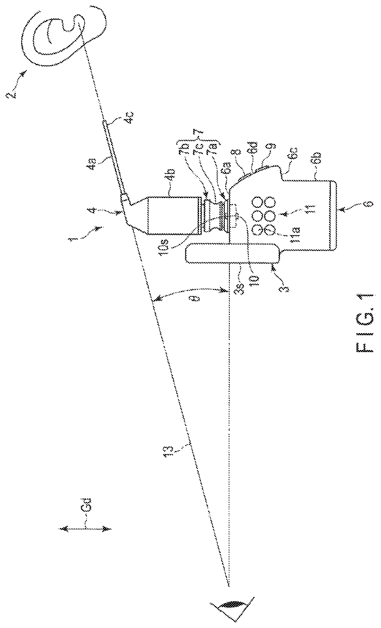
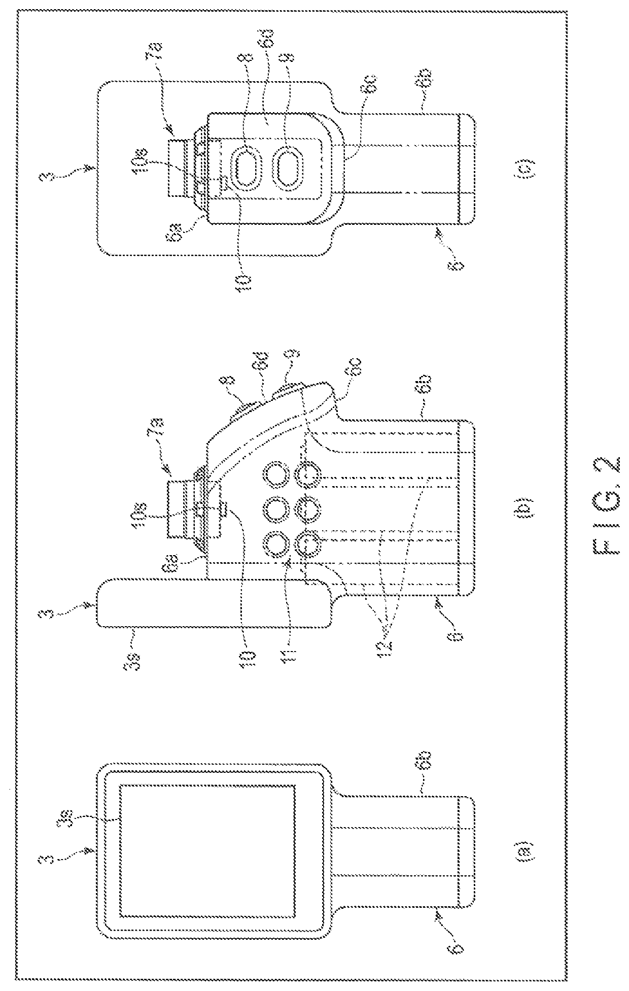
[0020]As shown in FIG. 1, a medical examination sight maintaining videoscope 1 of this embodiment makes it possible to shoot and record an object to be examined 2 and visualize the object to be examined 2 on a monitor 3 (display surface 3s) while maintaining the object to be examined 2 within the sight. Here, as the object to be examined 2, various cavities of a human body such as an aural cavity, oral cavity, nasal cavity, and the like can be assumed. The videoscope 1 includes a plurality of types of dedicated examination attachments 4 and 5 (see FIG. 5 and FIG. 6) configured to examine these cavities.

[0021]As one example, in FIG. 5, an aural cavity examination attachment 4 is shown. The aural cavity examination attachment 4 is provided with an aural cavity insertion section 4a which can ...


PUM


Abstract

In a medical examination sight maintaining videoscope of the present invention, in a state where an examination attachment is attached, it becomes possible to position a scope tip-end section and an object to be examined in a positional relationship in which the scope tip-end section and the object to be examined are straightly aligned with a line of sight of the user. At this time, a monitor is situated at such a position that the user can look straight at the monitor and the line of sight of the user is avoided.

Description

CROSS-REFERENCE TO RELATED APPLICATIONS[0001]This application is a Continuation Application of PCT Application No. PCT / JP2018 / 000495, filed Jan. 11, 2018 and based upon and claiming the benefit of priority from prior Japanese Patent Application No. 2017-046207, filed Mar. 10, 2017, the entire contents of all of which are incorporated herein by reference.BACKGROUND OF THE INVENTION1. Field of the Invention[0002]The present invention relates to a technique making it possible to shoot and record an object to be examined and visualize the object to be examined on a monitor while maintaining the object to be examined, for example, an aural cavity, oral cavity, nasal cavity or the like within a range (i.e., sight) in which the object can actually be viewed.2. Description of the Related Art[0003]A videoscope is known as a tool configured to optically observe an object to be examined such as an aural cavity, oral cavity, nasal cavity or the like (as in Patent Literature 1 (JP 2005-519666 A)...

Claims


Application Information

Patent Timeline
Patent Type & Authority Patents(United States)
IPC IPC(8): A61B1/227A61B1/06A61B1/00A61B1/24A61B1/233A61B1/04G02B23/24
CPCA61B1/00A61B1/06A61B1/00045G02B23/24A61B1/233A61B1/227A61B1/24A61B1/042A61B1/04A61B1/00066A61B1/00052A61B1/00042A61B1/00105A61B1/00048G02B23/2476
Inventor IWAMA, TAKESHI
Owner MPI INC
Why Eureka
Try Eureka