
Cardiovascular access and device delivery system

a technology which is applied in the field of cardiac access and device delivery system, can solve the problems of difficult closure of heart puncture, increased trauma to patients, and complex devices such as aortic valves delivered using catheters

Active Publication Date: 2020-09-01
CEDARS SINAI MEDICAL CENT
View PDF148 Cites 6 Cited by
  • Summary
  • Abstract
  • Description
  • Claims
  • Application Information

AI Technical Summary

Benefits of technology

The patent text describes methods and systems for accessing the heart through the apical wall of the heart and through a peripheral blood vessel to create a trans-cardiac rail for delivering a prosthesis or other implant. The methods provide low-profile access for creating the rail and can be used to treat various heart conditions. The text also describes a device for closing the cardiac access channel. The technical effects of the patent text include improved access for heart treatment and the ability to close the cardiac access channel after use.

Problems solved by technology

In recent years, complex devices such as aortic valves have been delivered using catheters.
These surgical approaches provide various disadvantages, however.
To the extent large devices are delivered through this enlarged surgical window, trauma to the patient is increased and closure of the heart puncture is challenging.

Method used


Image

  • Cardiovascular access and device delivery system
  • Cardiovascular access and device delivery system
  • Cardiovascular access and device delivery system

Examples


Embodiment Construction

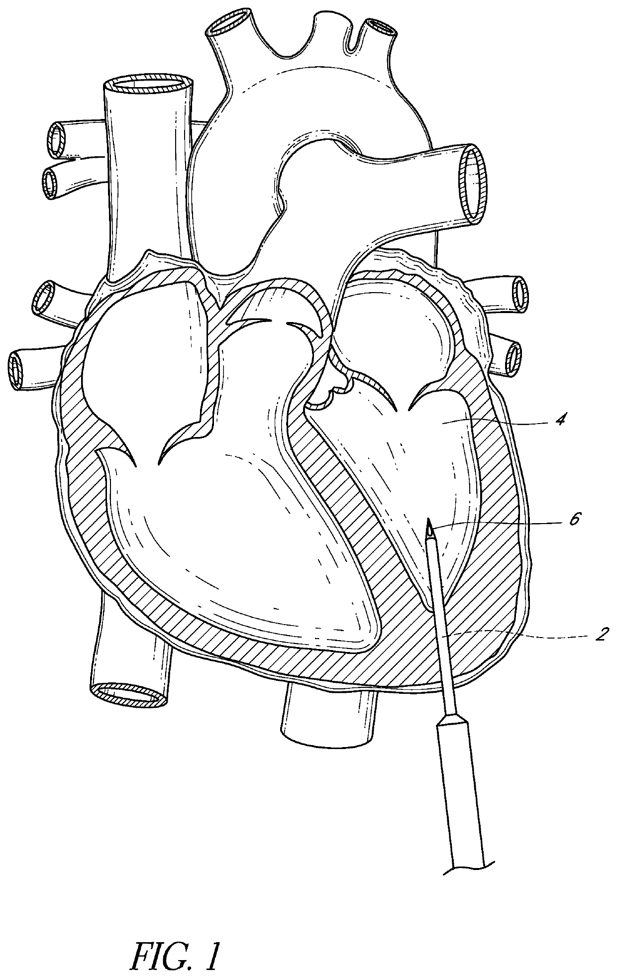
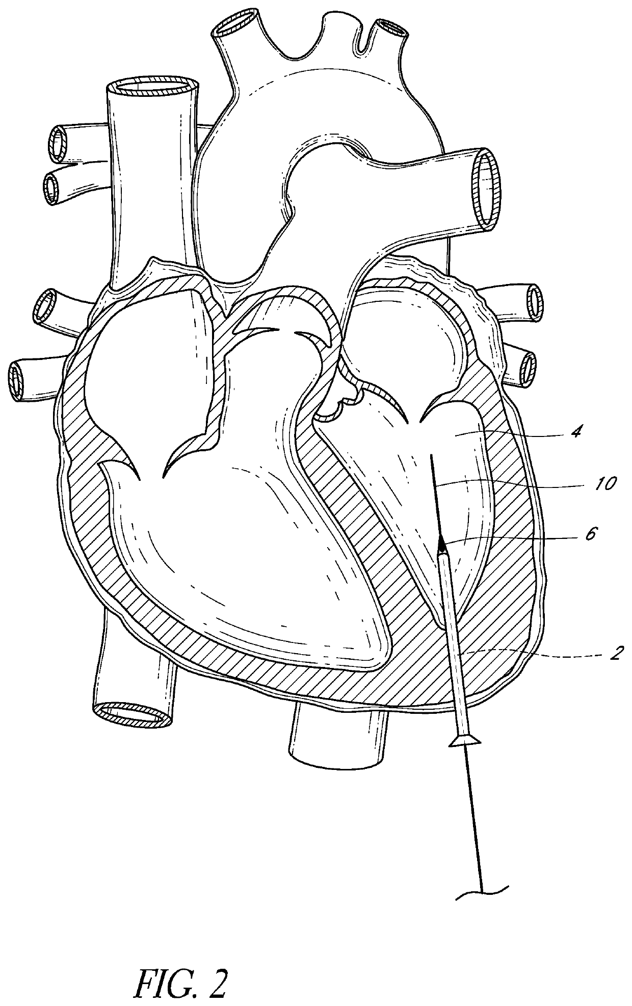
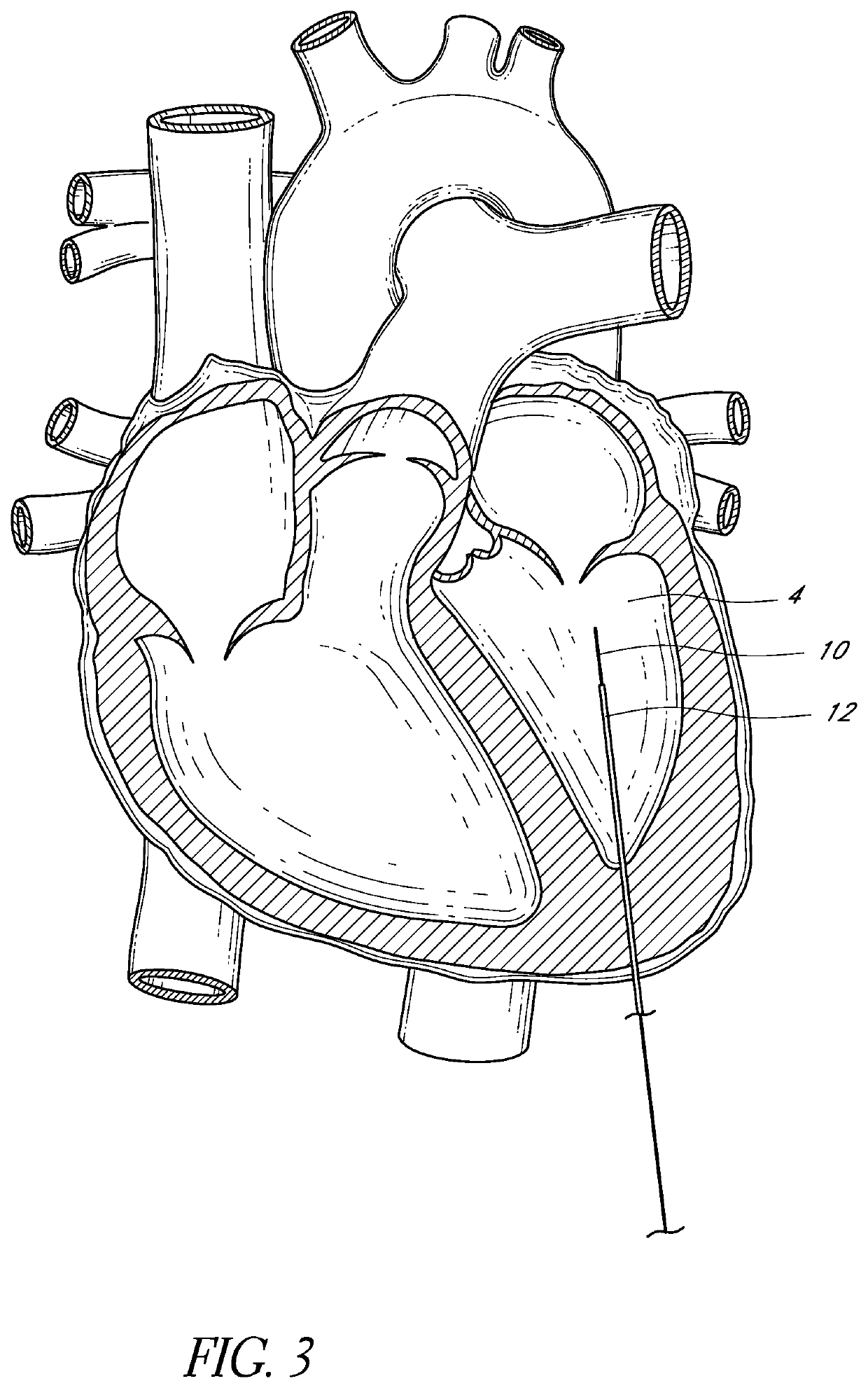
[0030]This application discloses various system and methods for providing a rail structure for guiding the advancement and deployment of cardiac prostheses or therapy devices. The rail structure preferably has two or more ends that are externalized. Externalized ends may include portions that are disposed outside the body, such as through percutaneous vascular access device or through direct cardiac access device. Intracorporeal lengths of the rail may be disposed between the externalized ends. FIGS. 1-5 illustrate systems and methods that provide a rail structure between a direct heart access and a peripheral blood vessel access site. FIG. 6 shows a variation where a rail structure is disposed between a direct heart access and a peripheral arterial access. FIGS. 7-14 illustrate systems and methods for closing a heart wall puncture. FIGS. 15-19 illustrate systems and methods that can be used to provide a rail between an externalized end at a peripheral venous site and an externalize...


PUM


Abstract

A system and method of accessing a heart of a patient is provided. A cardiac access channel is established through an apical wall of the heart to provide direct access through the apical wall to the left ventricle. A vascular access channel is established through the skin to a peripheral blood vessel. A first end of an elongate member is advanced from the outside of the apical wall through the cardiac access channel and into the left ventricle. A second end disposed opposite the first end remains outside the patient. The elongate member is drawn into and through the vascular access channel to externalize the first end of the elongate member while leaving the second end outside the apical wall of the heart.

Description

CROSS-REFERENCE TO RELATED APPLICATIONS[0001]This application is a national stage application under 35 U.S.C. § 371 of International Application No. PCT / US2015 / 060726, filed on Nov. 13, 2015, which published in English as WO 2016 / 077783 A1 on May 19, 2016, and which claims priority benefit of U.S. Patent Application No. 62 / 079,811, filed on Nov. 14, 2014.BACKGROUND OF THE INVENTIONField of the Invention[0002]This application is directed to systems and methods for accessing heart chambers or major blood vessels to facilitate delivering and implanting devices or performing therapies therein.Description of the Related Art[0003]Catheters are in widespread use for a wide number of procedures. In recent years, complex devices such as aortic valves have been delivered using catheters. These catheter based procedures provide benefits for patients, including reduced trauma compared to surgical techniques for accomplishing similar outcomes, e.g., aortic valve replacement.[0004]Limitations of ...

Claims


Application Information

Patent Timeline
Patent Type & Authority Patents(United States)
IPC IPC(8): A61B17/34A61F2/24A61B17/00
CPCA61F2/2427A61B17/3421A61B17/0057A61B17/00234A61B2017/00247A61B2017/00623A61B2017/3425A61B2017/00243A61B2017/00632
Inventor SIEGEL, ROBERT JAMES
Owner CEDARS SINAI MEDICAL CENT
Learn More