Stretchable sheet, worn article using the same, and stretchable sheet manufacturing apparatus

a technology of stretchable sheet and manufacturing apparatus, which is applied in the direction of other domestic articles, transportation and packaging, bands, etc., can solve the problems of lowering the production yield and quality of stretchable sheet, affecting the quality of product, and possibly excessive pressure on elastic members to be broken, so as to achieve good stretchability, improve the production yield of stretchable sheet, and improve the quality of product

Active Publication Date: 2020-09-01
ZUIKO CORP
View PDF16 Cites 3 Cited by
  • Summary
  • Abstract
  • Description
  • Claims
  • Application Information

AI Technical Summary

Benefits of technology

[0004]One method for securing elastic members is a method of pressing sheets against the elastic members while the sheets are heated. If one increases the width of the attached portions in order to firmly secure the elastic members on the sheets, the sheets will be heated with an increased surface pressure over a wide attachment range. In such a case, the elastic members may be possibly excessively pressurized and heated to be broken. This will likely lower the production yield and the quality of the stretchable sheet.
[0005]Thus, it is an object of the present invention to provide a stretchable sheet, a worn article and a stretchable sheet manufacturing apparatus, with which it is possible to reduce securing failure and breakage of the attached portions, thereby improving the production yield and the quality of the product.

Problems solved by technology

In such a case, the elastic members may be possibly excessively pressurized and heated to be broken.
This will likely lower the production yield and the quality of the stretchable sheet.

Method used


Image

  • Stretchable sheet, worn article using the same, and stretchable sheet manufacturing apparatus
  • Stretchable sheet, worn article using the same, and stretchable sheet manufacturing apparatus
  • Stretchable sheet, worn article using the same, and stretchable sheet manufacturing apparatus

Examples


embodiment 1

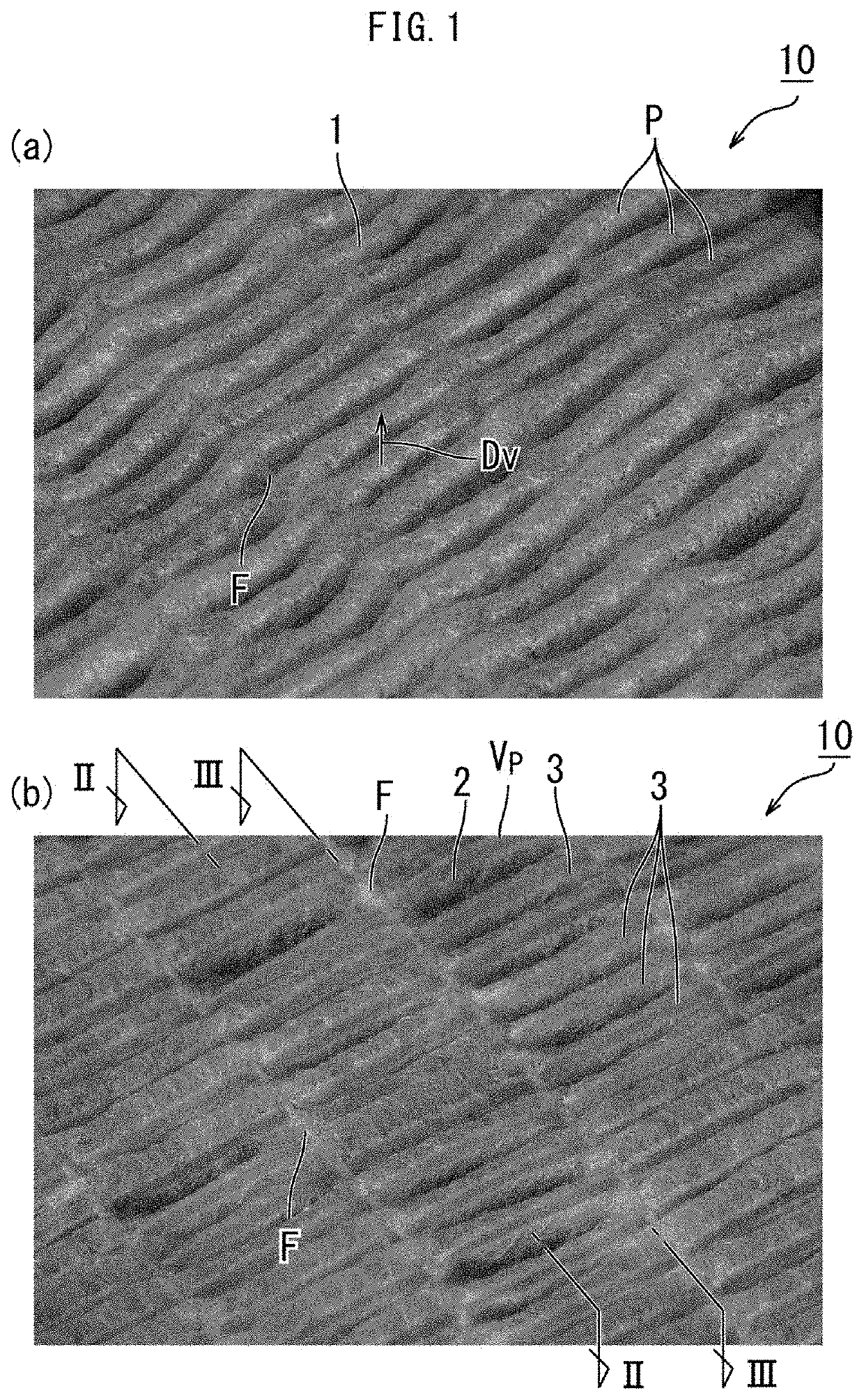
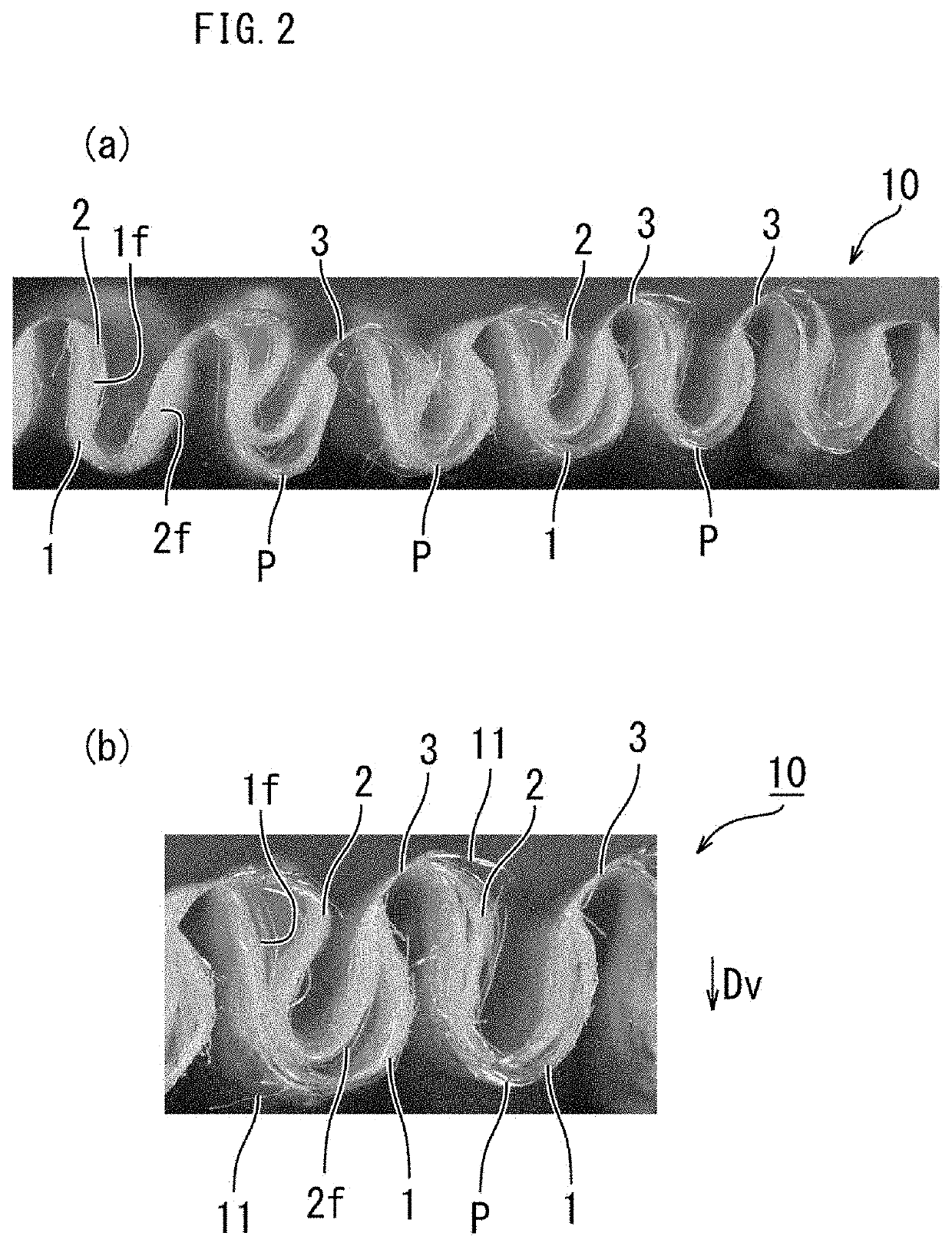
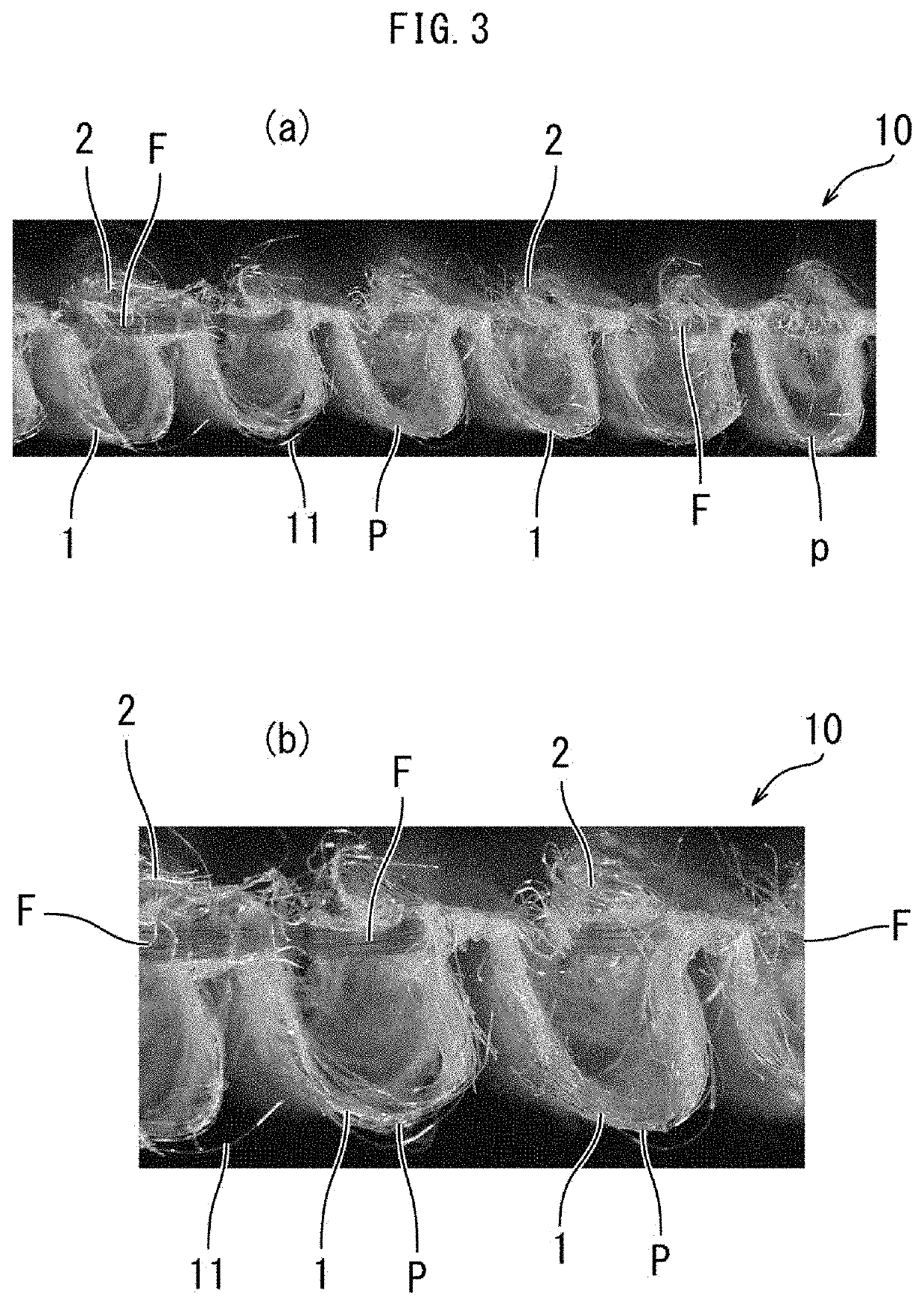
[0100]Next, Embodiment 1 of the stretchable sheet 10 will be described.

[0101]First, a state where the elastic members F are stretched will be described.

[0102]As shown in FIG. 11C, the first surfaces 1f and 2f of the pair of sheets 1 and 2 oppose each other or are in contact with each other. The plurality of elastic members F are arranged between the first surfaces 1f and 2f of the pair of sheets 1 and 2, and are arranged spaced apart from each other as indicated by broken lines in FIG. 11B.

[0103]As shown in FIG. 11B and FIG. 11C, the pair of sheets 1 and 2 are attached to each other by being welded (structure), without using an adhesive, at a plurality of attached portions 3. In the present example, the pair of sheets 1 and 2 are welded to the elastic members F at the attached portions 3, thereby securing the elastic members F to the pair of sheets 1 and 2 at the attached portions 3.

[0104]The attached portions 3 are formed (attached by a welded structure) as the pair of sheets 1 and...

embodiment 2

[0148]FIG. 5 to FIG. 8, FIG. 10 and FIG. 12A show

[0149]In the present embodiment, as shown in FIGS. 8(a) and 8(b) and FIG. 12A, the attached portions 3 include a plurality of first attached portions 31 and a plurality of second attached portions 32. The first attached portions 31 extend in the first direction D1 crossing the direction of stretch Df of the elastic members F. The second attached portions 32 extend in the second direction D2 crossing the direction of stretch Df and the first direction D1.

[0150]As shown in FIG. 12A, in the present example, the width W3 of the attached portions 3 in the direction of stretch Df is measured diagonally with respect to the direction in which the attached portions 3 extend. The width W3 may be larger at positions where the first attached portion 31 and the second attached portion 32 intersect.

[0151]In the present example, in the state of FIG. 12A and FIG. 8(b) where the elastic members F are stretched, the area α1 is defined by the elastic me...

embodiment 3

[0155]FIG. 12B shows

[0156]Each attached portion 3 may be formed in a wave shape as in this example. In this case, although the attached portions 3 do not intersect each other, folds P of a similar shape to Embodiment 2 of FIG. 12A will be formed.

[0157]In the examples of FIG. 11B to FIG. 12B, each attached portion 3 is continuous and crosses the elastic members F, and the pair of sheets 1 and 2 (FIG. 11C) are welded to the elastic members F at positions where the elastic members F extend.

[0158]However, each attached portion 3 may be non-continuous as shown in FIG. 12C and FIG. 12D. The pair of sheets 1 and 2 do not need to be welded to the elastic members F at positions where the elastic members F of FIG. 12C extend. That is, the attached portions 3 and the elastic members F do not need to overlap with each other, and the attached portions 3 may extend continuously or intermittently.

[0159]In the case of the example of FIG. 12C, the opposite ends of the elastic members F may be secure...


PUM

PropertyMeasurementUnit
widthaaaaaaaaaa
widthaaaaaaaaaa
width W2aaaaaaaaaa

Abstract

A stretchable sheet 10 includes: a plurality of attached portions 3 spaced apart from each other in the direction of stretch Df, wherein the first surfaces 1f and 2f of a pair of sheets 1 and 2 are attached to each other by being welded without using an adhesive, at the attached portions 3, the attached portions 3 hold elastic members F, and the attached portions 3 extend in a direction Dp crossing the direction of stretch Df of the elastic members F; and a plurality of folds P that appear between the attached portions 3 while the elastic members F are shrunk, wherein a width W3 of the attached portions 3 in the direction of stretch Df is set to be 0.2 mm or more and less than 1.0 mm.

Description

TECHNICAL FIELD[0001]The present invention relates to a stretchable sheet, a worn article using the same, and a stretchable sheet manufacturing apparatus.BACKGROUND ART[0002]A structure in which a plurality of elastic members are sandwiched between two sheets, wherein the two sheets are welded together and elastic members are secured between the two sheets at attached portions that extend in a direction crossing the direction of stretch of the elastic members, is known in the art as a structure of a stretchable sheet (first patent document).CITATION LISTPatent Literature[0003][First Patent Document] JP2014-198180A (front page)SUMMARY OF INVENTION[0004]One method for securing elastic members is a method of pressing sheets against the elastic members while the sheets are heated. If one increases the width of the attached portions in order to firmly secure the elastic members on the sheets, the sheets will be heated with an increased surface pressure over a wide attachment range. In su...

Claims


Application Information

Patent Timeline
Patent Type & Authority Patents(United States)
IPC IPC(8): A61F13/49B32B3/28B32B7/05A61F13/514A61F13/513
CPCA61F13/49B32B3/28A61F13/49009B32B2555/02B32B7/05A61F2013/51322A61F2013/51429Y10T428/24Y10T428/24025Y10T428/24033A61F13/15699A61F13/4902A61F13/15747A61F13/15593A61F13/51104A61F13/513A61F13/51464A61F13/51476A61F2013/49023A61F2013/15878
Inventor NAKAMURA, HIDEYUKIKOSHIJIMA, MIWA
Owner ZUIKO CORP
Why Eureka
Try Eureka