Vacuum transfer module and substrate processing apparatus

a technology of transfer module and substrate, which is applied in the direction of electric devices, conveyor parts, transportation and packaging, etc., can solve the problems of difficulty in sufficiently reducing the footprint of the apparatus, and achieve the effect of increasing the degree of freedom

Active Publication Date: 2020-09-01
TOKYO ELECTRON LTD
View PDF14 Cites 197 Cited by
  • Summary
  • Abstract
  • Description
  • Claims
  • Application Information

AI Technical Summary

Benefits of technology

[0006]In view of the above, the present disclosure provides a technique for increasing a degree of freedom in the arrangement of load-lock modules connected to a vacuum transfer module for transferring a substrate in a vacuum atmosphere and a plurality of processing modules for processing the substrate in the vacuum atmosphere.

Problems solved by technology

Japanese Patent Application Publication No. 2013-171872 does not disclose a measure for solving the problem of the degree of freedom in the arrangement.
However, as the number of processing modules is increased, the number of transfer modules is also increased and, thus, it is difficult to sufficiently reduce the footprint of the apparatus.

Method used


Image

  • Vacuum transfer module and substrate processing apparatus
  • Vacuum transfer module and substrate processing apparatus
  • Vacuum transfer module and substrate processing apparatus

Examples


first embodiment

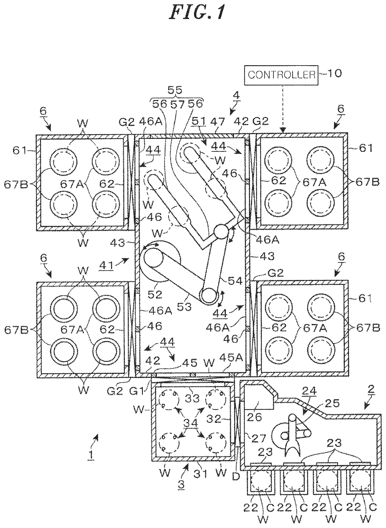
[0028]A substrate processing apparatus 1 according to a first embodiment will be described with reference to the top view in FIG. 1. The substrate processing apparatus 1 includes a loader module 2, a load-lock module 3, a vacuum transfer module 4, and processing modules 6. The loader module 2 and the load-lock module 3 are connected to each other in a horizontal direction. The load-lock module 3 and the vacuum transfer module 4 are connected to each other in the horizontal direction. The vacuum transfer module 4 and the processing modules 6 are connected to each other in the horizontal direction. Since FIG. 1 is the top view, the load-lock module 3 and the vacuum transfer module 4 are arranged in the up down direction in the drawing.

[0029]The loader module 2 is used for taking, out a wafer W that is a circular substrate having a diameter of, e.g., 300 mm, from a carrier C that is a transfer container where the wafer W is stored in a normal pressure atmosphere. There are four process...

second embodiment

[0065]A substrate processing apparatus 81 according to a second embodiment will be described with reference to FIG. 6. Here, the differences between the substrate processing apparatus 81 and the substrate processing apparatus 1 will be described mainly. A vacuum transfer module 4 of the substrate processing apparatus 81 is provided such that long sides thereof extend along the right-left direction when seen from the top. A processing module 6 is attached to each of two first sidewalls 42 of the vacuum transfer module 4 through an interface plate 46. Two processing modules 6 are attached to second sidewall 43 on the rear side through interface plates 46. In the second sidewall 43 on the front side, a blind plate 47 is attached to a right opening 44, and a load-lock module 3 is attached to a left opening 44 through an interface plate 45.

[0066]FIG. 7 snows an example in which four substrate processing apparatuses 81 are arranged in a 2×2 matrix shape as in the first embodiment. In two ...

third embodiment

[0068]A substrate processing apparatus 82 according to a third embodiment will be described with reference to FIG. 8. Here, the differences between the substrate processing apparatus 82 and the substrate processing apparatus 1 will be described mainly. FIG. 8 shows an example in which the apparatuses are arranged in a 2×2 matrix shape as in the case of the substrate processing apparatuses 1 shown in FIG. 5 and the substrate processing apparatuses 81 shown in FIG. 7. Reference numerals 82A to 82D are given to the apparatuses in the above-described manner. In the vacuum transfer module 4 of the substrate processing apparatus 82, the processing module 6 also connected to the first sidewall 42 on the rear side. Further, one processing module 6 and a blind plate 47 are attached to one of the two second sidewalls 43.

[0069]In the substrate processing apparatuses 82A and 82B, the second sidewalls 43 to each of which one processing module 6 is connected face each other, and the positions of ...


PUM


Abstract

A vacuum transfer module, to which a load-lock module and a plurality of processing modules for processing substrate in a vacuum atmosphere are connected, has therein a substrate transfer unit for transferring the substrate between the load-lock module and the plurality of processing modules. The vacuum transfer module includes: a housing in which a vacuum atmosphere is generated; and a plurality of adaptor attaching portions to which one of a first adaptor for connecting the load-lock module and a second adaptor for connecting the plurality of processing modules is attached, provided at a sidewall of the housing. The adaptor attaching portions are common for the first adaptor and the second adaptor.

Description

CROSS-REFERENCE TO RELATED APPLICATIONS[0001]This application claims priority to Japanese Patent Application Nos. 2017-102016 and 2017-188627 respectively filed on May 23 and Sep. 28, 2017, the entire contents of which are incorporated herein by reference.FIELD OF THE INVENTION[0002]The present disclosure relates to a technique for transferring a substrate in a vacuum atmosphere to process the substrate.BACKGROUND OF THE INVENTION[0003]In a semiconductor device manufacturing process, various processes such as etching, film formation and the like are performed in a vacuum atmosphere on a semiconductor wafer (hereinafter, referred to as “wafer”) that a substrate. A substrate processing apparatus for performing such processes on the substrate includes a processing module for generating a vacuum atmosphere and performing gas processing on the wafer and a load-lock module whose inner pressure can be changed to transfer the wafer between carrier of the wafer in a normal pressure atmospher...

Claims


Application Information

Patent Timeline
Patent Type & Authority Patents(United States)
IPC IPC(8): H01L21/677H01L21/67H01L21/68
CPCH01L21/67161H01L21/67745H01L21/67754H01L21/67781H01L21/67196H01L21/681H01L21/67742H01L21/67201H01L21/67184H01L21/67167H01L21/67769H01L21/67775
Inventor SHINDO, TAKEHIRO
Owner TOKYO ELECTRON LTD
Why Eureka
Try Eureka