Floating platform with 3 canted columns converged at center

a floating platform and center technology, applied in the field of floating platforms, can solve problems such as no longer valid requirements

Active Publication Date: 2020-09-08
ARGUS MARINE SOLUTIONS LLC
View PDF8 Cites 2 Cited by
  • Summary
  • Abstract
  • Description
  • Claims
  • Application Information

AI Technical Summary

Benefits of technology

[0003]A new concept according to Claim 1-10 provides a new platform shape. The concept is different from prior arts such as a battered column semisubmersible for oil and gas platform. The advantage of using canted columns converging to a central location over prior art is that it eliminates the deck structure, which was critical to offshore oil and gas facilities, by using the columns to directly support topsides or turbines and its foundation. The overall structure weight and VCG are reduced so that the platform is hydrostatically stable with topsides or wind turbines installed at quayside. This eliminates the need of offshore integration of wind turbine with hull at work site.
[0004]Traditional platform has very small inclination or no inclination in the column structure. The mooring lines have to departure at a certain angle to avoid mooring line interfering with the hull structure. For the canted column structures, due to inclination, the column inclination and pontoon side forms an angle. The mooring line's departure angle is not necessarily the same as column inclination angle. Therefore traditional fairlead will not function. The invented new fairlead will provide one additional wheel to allow lines to make one more turn before departure similar to traditional mooring lines. This additional wheel enables the mooring lines working properly for inclined column structure.
[0011]A wind platform can work fine with the above mentioned method, without chain jacks or mooring winch onboard of the platform, since the frequent changing of mooring length or change of platform position is not necessary. However, traditional oil and gas drilling or production units cannot use this method due to the fact that constant changing of mooring length may be required.

Problems solved by technology

However, for a wind turbine platform or a platform with small footprint topsides, this requirement is no longer valid.

Method used


Image

  • Floating platform with 3 canted columns converged at center
  • Floating platform with 3 canted columns converged at center
  • Floating platform with 3 canted columns converged at center

Examples


Embodiment Construction

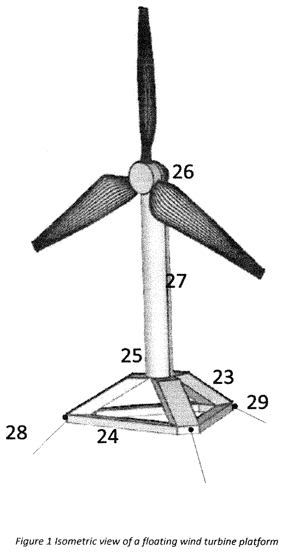
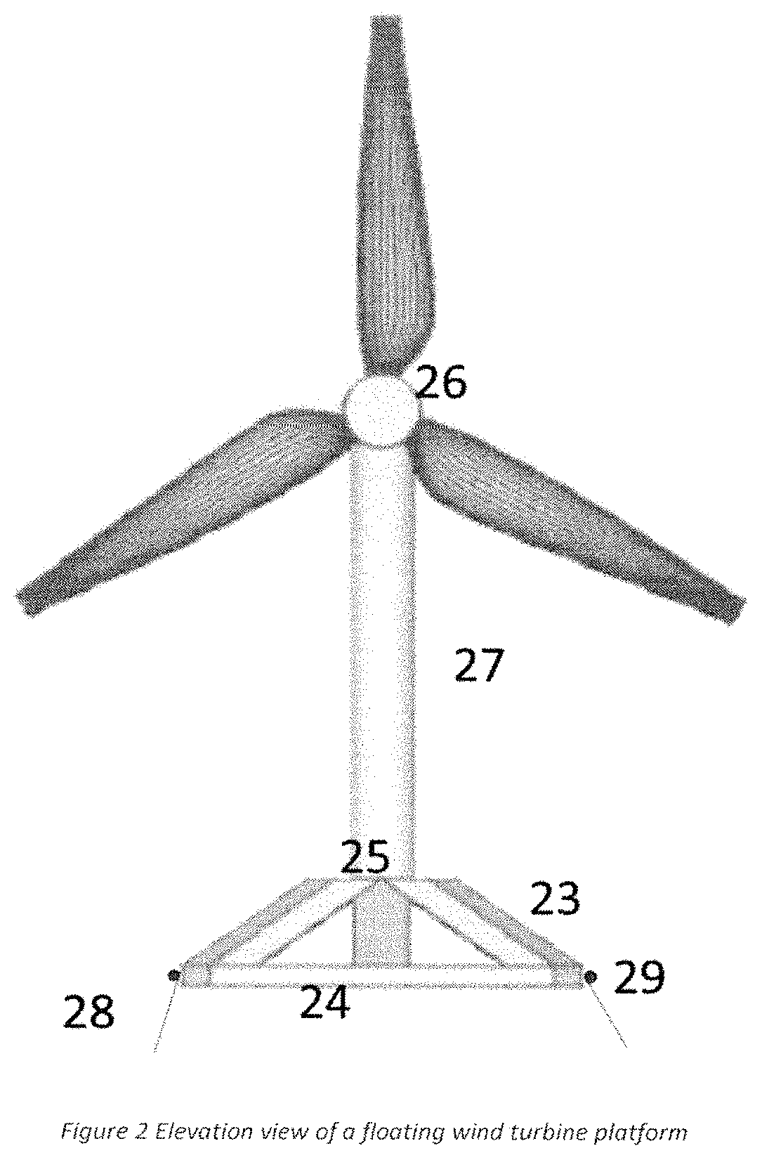
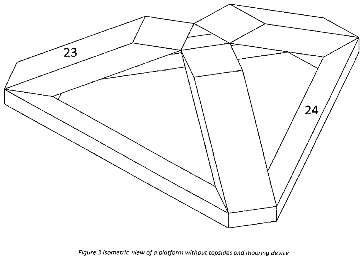
[0025]The components of the invention are:

[0026]A floating platform is with pontoon shape 24 and column 23. The platform can be with 3 pontoons as shown in FIG. 1 and FIG. 2, or 4 pontoons, or more pontoons that are not shown in the figures. The pontoon can be square, rectangular, or cylindrical, or other shapes. The column can be square, rectangular, or cylindrical, or other shapes. FIG. 1 shows rectangular pontoons and rectangular columns. On the top, there is foundation 25 supporting a turbine 26. The foundation 26 could be a truss type or box shape structure supporting turbine and tower 27. The foundation could be a pole supporting wind turbine, a deck structure supporting equipment, or other devices. Mooring lines 28 is shown to illustrate the station keeping. This can be catenary, taut, or even vertically tensioned up. It is attached to fairlead 29 on the hull. FIGS. 3 and 4 do not show any actual wind turbines or other devices for clarity, but the intention is to support abov...


PUM


Abstract

We have invented a floating platform with 3 canted columns, a new type of fairlead, and a new method of mooring line makeup and installation method, that can be used for canted columns. The platform includes 3 columns having upper ends projecting above water surface. The columns are canted or inclined inward from the corner of hull toward the central vertical axis. The 3 columns converge at the top of column such that each column will lean against the other 2 columns. Each column has two connection points to the other 2 columns. Horizontally disposed pontoons interconnect adjacent columns at the lower ends. The columns and pontoons form a closed structure hull to support a foundation structure directly above the top of column.

Description

[0001]The present application claims priority to the earlier filed provisional application “Floating Platform with 3 Canted Columns Converged at Center” having application No. 62 / 661,033, and hereby incorporates subject matter of the provisional application in its entirety.TECHNICAL FIELD AND BACKGROUND OF THE INVENTION[0002]There are floating platforms with small footprint topsides, such as wind turbine platforms. The platforms are with vertical columns. The vertical columns provide stability of the platforms. U.S. Pat. No. 8,196,539 Battered Column Offshore Platform shows a semisubmersible with battered columns. One embodiment of the invention is a semisubmersible with 3 columns. It is connected at column bottom by pontoons and decks on the column top. In the invention, the battered columns and pontoons form an open hull to support the deck. The columns do not converge to a central location to connect with each other. This open hull can provide support to a deck with large surface...

Claims


Application Information

Patent Timeline
Patent Type & Authority Patents(United States)
IPC IPC(8): B63B35/44B63B35/38F03D13/25B63B21/50
CPCB63B35/4413B63B35/38B63B21/502F03D13/25B63B35/44F05B2240/95B63B2035/446B63B2001/128F05B2240/93Y02E10/72Y02E10/727Y02P70/50
Inventor LI, TINGTINGFENG, NANYANG, YUMIN
Owner ARGUS MARINE SOLUTIONS LLC
Why Eureka
Try Eureka