Supercharge Your Innovation With Domain-Expert AI Agents!

Exhaust gas recirculation compressor inlet thermal separation system

a compressor and gas recirculation technology, applied in the field of automotive, can solve the problems of compromising emissions testing, limiting the use of egr gas, and affecting the normal activation of the egr system,

Active Publication Date: 2020-09-08
VOLVO CAR CORP
View PDF7 Cites 1 Cited by
  • Summary
  • Abstract
  • Description
  • Claims
  • Application Information

AI Technical Summary

Benefits of technology

[0006]The exhaust gas recirculation (EGR) system provided herein utilizes an insulated separation wall that separates the hot, humid EGR gas duct from the cool, dry inlet air duct in the upstream proximity of the compressor inlet of the associated turbocharger compressor. This insulated separation wall inhibits the condensation of water droplets and the formation of ice particles near the mixing point of the EGR gases and inlet air in the upstream proximity of the compressor inlet, such that the turbocharger compressor wheel, blades, and other components are not subsequently damaged by the condensed water droplets or formed ice particles. The added insulation in this cold sink area essentially thermally isolates the hot, humid EGR gas flow from the cool, dry inlet air flow until the actual mixing point of the flows.

Problems solved by technology

The utilization of EGR gases, however, is often limited by the condensation of water droplets in the EGR gases near the mixing point as the hot, humid EGR gases are cooled by the cool, dry inlet air.
This problem is especially pronounced under cold start and low temperature operating conditions, sometimes delaying the normal activation of the EGR system.
This can compromise emissions testing results, for example, and otherwise degrade engine performance.
In a worst case scenario, under extreme conditions, ice particles can even be formed in the EGR gases, exacerbating these issues.
Problematically, the condensed water droplets (or ice particles) near the mixing point of the EGR gases and the inlet air are fed directly to the turbocharger compressor.
These water droplets (or ice particles) can impact the turbocharger compressor wheel, blades, and other components, damaging them.
This force exerted parallel to the component surface can impinge upon surface imperfections, causing spalls, cracks, etc. at or near such surface imperfections.

Method used


Image

  • Exhaust gas recirculation compressor inlet thermal separation system
  • Exhaust gas recirculation compressor inlet thermal separation system
  • Exhaust gas recirculation compressor inlet thermal separation system

Examples


Embodiment Construction

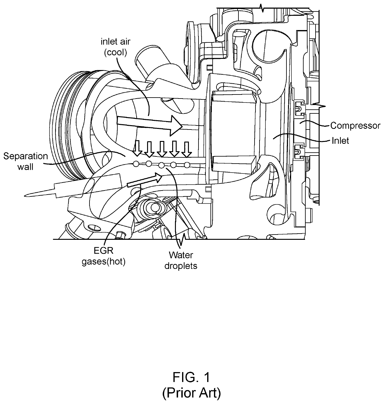
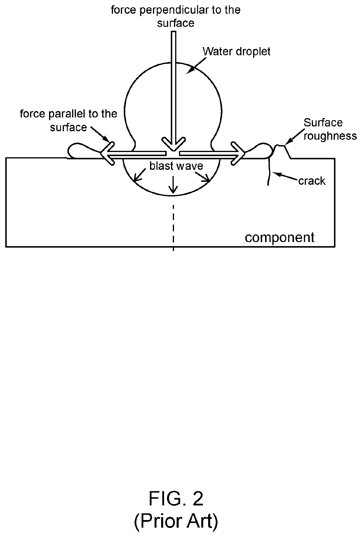
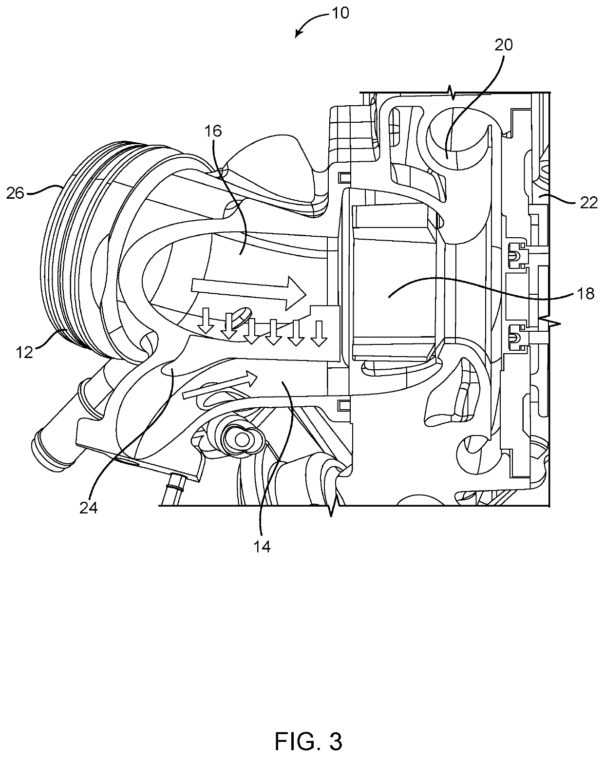
[0019]Again, the exhaust gas recirculation (EGR) system provided herein utilizes an insulated separation wall that separates the hot, humid EGR gas duct from the cool, dry inlet air duct in the upstream proximity of the compressor inlet of the associated turbocharger compressor. This insulated separation wall inhibits the condensation of water droplets and the formation of ice particles near the mixing point of the EGR gases and inlet air in the upstream proximity of the compressor inlet, such that the turbocharger compressor wheel, blades, and other components are not subsequently damaged by the condensed water droplets or formed ice particles. The added insulation in this cold sink area essentially thermally isolates the hot, humid EGR gas flow from the cool, dry inlet air flow until the actual mixing point of the flows.

[0020]Referring now specifically to FIGS. 3-7, in one exemplary embodiment, the EGR thermal separation system 10 includes a ported shroud 12 that defines both an E...


PUM


Abstract

An exhaust gas recirculation (EGR) system that utilizes an insulated separation wall that separates the hot, humid EGR gas duct from the cool, dry inlet air duct in the upstream proximity of the compressor inlet of the associated turbocharger compressor. This insulated separation wall inhibits the condensation of water droplets and the formation of ice particles near the mixing point of the EGR gases and inlet air in the upstream proximity of the compressor inlet, such that the turbocharger compressor wheel, blades, and other components are not subsequently damaged by the condensed water droplets or formed ice particles. The added insulation in this cold sink area essentially thermally isolates the hot, humid EGR gas flow from the cool, dry inlet air flow until the actual mixing point of the flows.

Description

TECHNICAL FIELD[0001]The present invention relates generally to the automotive field. More specifically, the present invention relates to an exhaust gas recirculation (EGR) compressor inlet thermal separation system configured to reduce the level of condensation in the exhaust gases recirculated to the associated turbocharger compressor inlet.BACKGROUND ART[0002]As fuel efficiency and emissions concerns become increasingly important, more and more vehicles are being equipped with turbochargers utilizing exhaust gas recirculation (EGR) systems. EGR systems increase the fuel efficiency of an internal combustion (IC) engine and reduce the emissions of noxious exhaust gases by recirculating a portion of the unused fuel and exhaust gases back to the engine for use, instead of releasing them into the environment. In a low pressure (LP) EGR system, the exhaust gases are reintroduced to the engine just upstream of the turbocharger compressor, at the turbocharger compressor inlet. At this lo...

Claims


Application Information

Patent Timeline
Patent Type & Authority Patents(United States)
IPC IPC(8): F04D29/58F04D17/10F02B33/40F04D29/40
CPCF04D29/5853F04D29/403F04D17/10F02B33/40F02M26/04F02M26/18F02M26/19F05D2220/40F04D29/4213
Inventor ROLANDSON, OLA
Owner VOLVO CAR CORP
Features
  • R&D
  • Intellectual Property
  • Life Sciences
  • Materials
  • Tech Scout
  • Unparalleled Data Quality
  • Higher Quality Content
  • 60% Fewer Hallucinations
Learn More