Cuff pressure controller device
a controller device and cuff technology, applied in the field of cuff pressure controller devices, can solve the problems of reducing work efficiency and taking a long time to inflate the cuff for the first time, and achieve the effects of reducing the size of the device body, high discharge pressure, and large discharge flow volum
- Summary
- Abstract
- Description
- Claims
- Application Information
AI Technical Summary
Benefits of technology
Problems solved by technology
Method used
Image
Examples
first embodiment
of the Present Disclosure
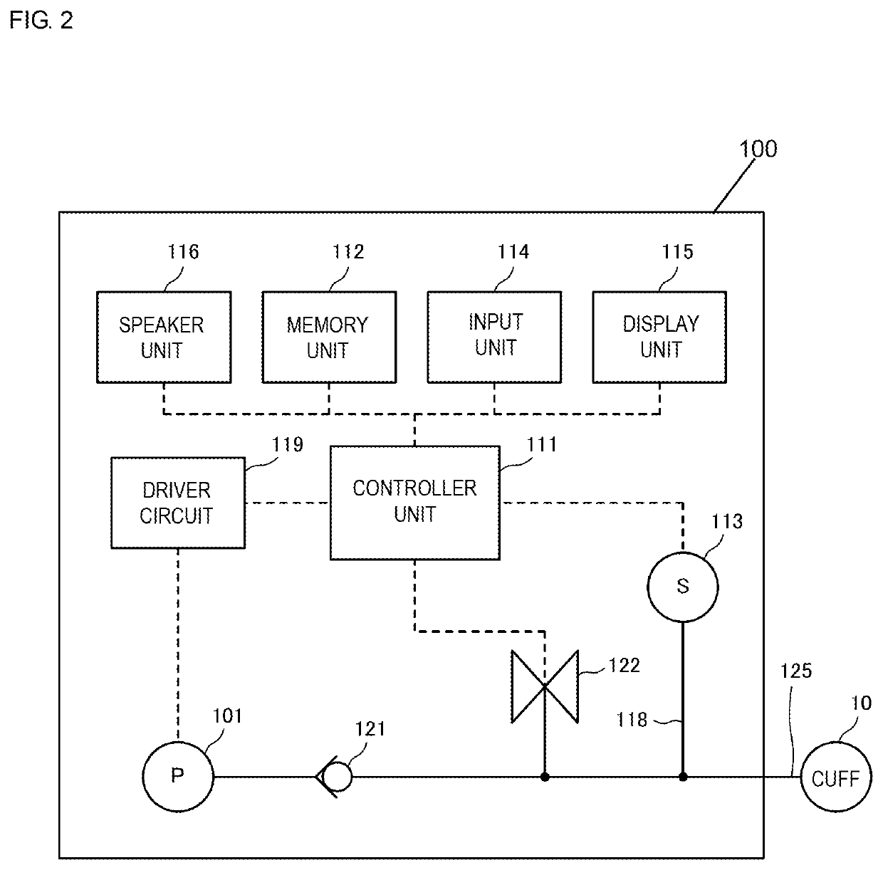
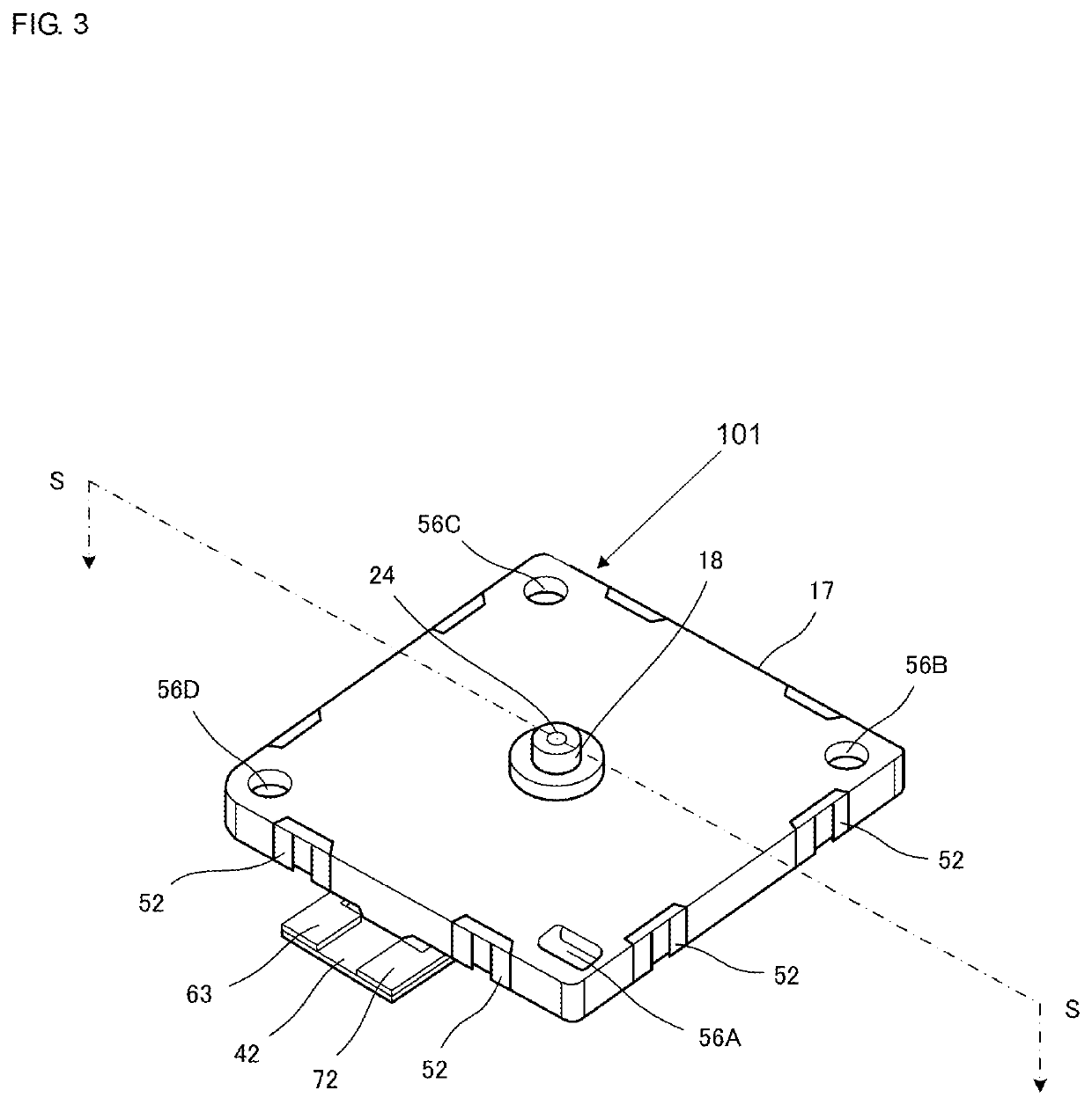
[0069]A cuff pressure controller device 100 according to the first embodiment of the present disclosure is now described below.
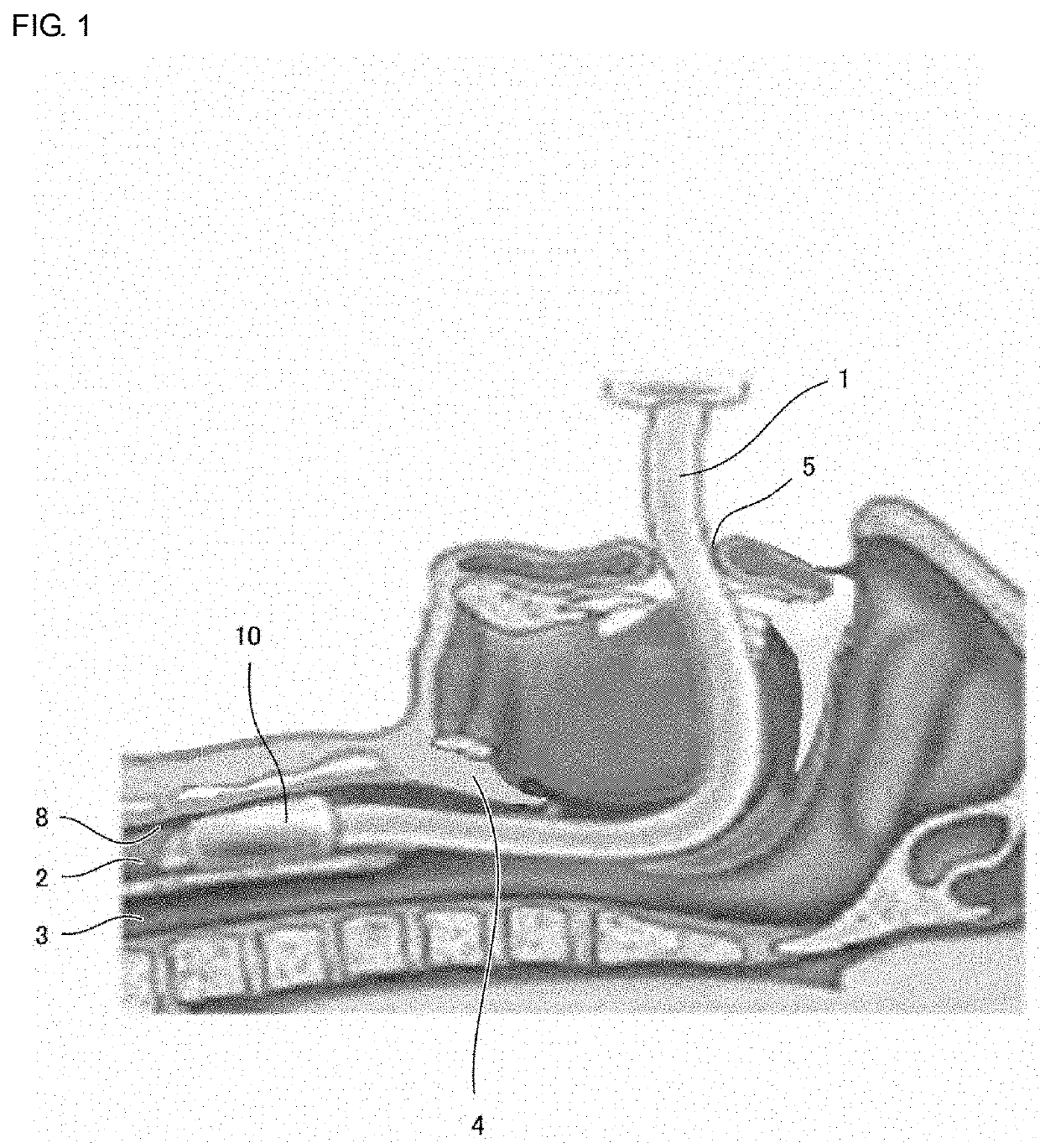
[0070]FIG. 1 is a schematic diagram depicting how an intubation tube is inserted into trachea through cavity of mouth.
[0071]In the case where tracheal intubation is performed to secure airway during the usage of artificial ventilators, when there is a gap between an intubation tube 1 inserted through cavity of mouth 5 and an inner wall 8 of trachea 2, secretions from esophagus 3 such as gastric fluid, saliva, and the like enters trachea 2, causing a subject to be at a high risk of developing ventilator-associated pneumonia (hereinafter, referred to as “VAP”). Particularly, during the tracheal intubation, epiglottis 4 is kept open, and gastric fluid from esophagus 3 is likely to enter trachea 2.
[0072]To block such secretion inflow, a cuff 10 is provided at a predetermined location of an outer periphery of the intubation tube 1. This c...
second embodiment
of the Present Disclosure
[0116]A cuff pressure controller device 100 according to the second embodiment of the present disclosure is now described below.
[0117]The cuff pressure controller device of the second embodiment differs from the cuff pressure controller device 100 of the first embodiment in having a piezoelectric pump 201 instead of the piezoelectric pump 101. The remaining configuration is the same as that of the first embodiment. Thus, the redundant description is omitted.
[0118]The structure of the piezoelectric pump 201 is described in detail with reference to FIG. 7 and FIG. 8.
[0119]FIG. 7 is an exploded perspective view of the piezoelectric pump 201 according to the second embodiment of the present disclosure. FIG. 8 is a cross-sectional diagram of relevant part of the piezoelectric pump 201 depicted in FIG. 7.
[0120]A substrate 291, a flexible plate 251, a spacer 253A, a reinforcing plate 243, a vibration plate unit 260, a piezoelectric element 242, a spacer 253B, an el...
PUM
 Abstract
Description
Claims
Application Information
 - R&D
- Intellectual Property
- Life Sciences
- Materials
- Tech Scout
- Unparalleled Data Quality
- Higher Quality Content
- 60% Fewer Hallucinations
Browse by: Latest US Patents, China's latest patents, Technical Efficacy Thesaurus, Application Domain, Technology Topic, Popular Technical Reports.
© 2025 PatSnap. All rights reserved.Legal|Privacy policy|Modern Slavery Act Transparency Statement|Sitemap|About US| Contact US: help@patsnap.com


