Control device and inspection device
a control device and inspection device technology, applied in the direction of visual presentation using printers, instruments, image enhancement, etc., can solve the problem of difficult to accurately extract grayscale color based on hsv values, and achieve the effect of accurate extraction of specific color pixels and more precise processing
- Summary
- Abstract
- Description
- Claims
- Application Information
AI Technical Summary
Benefits of technology
Problems solved by technology
Method used
Image

Examples
first embodiment
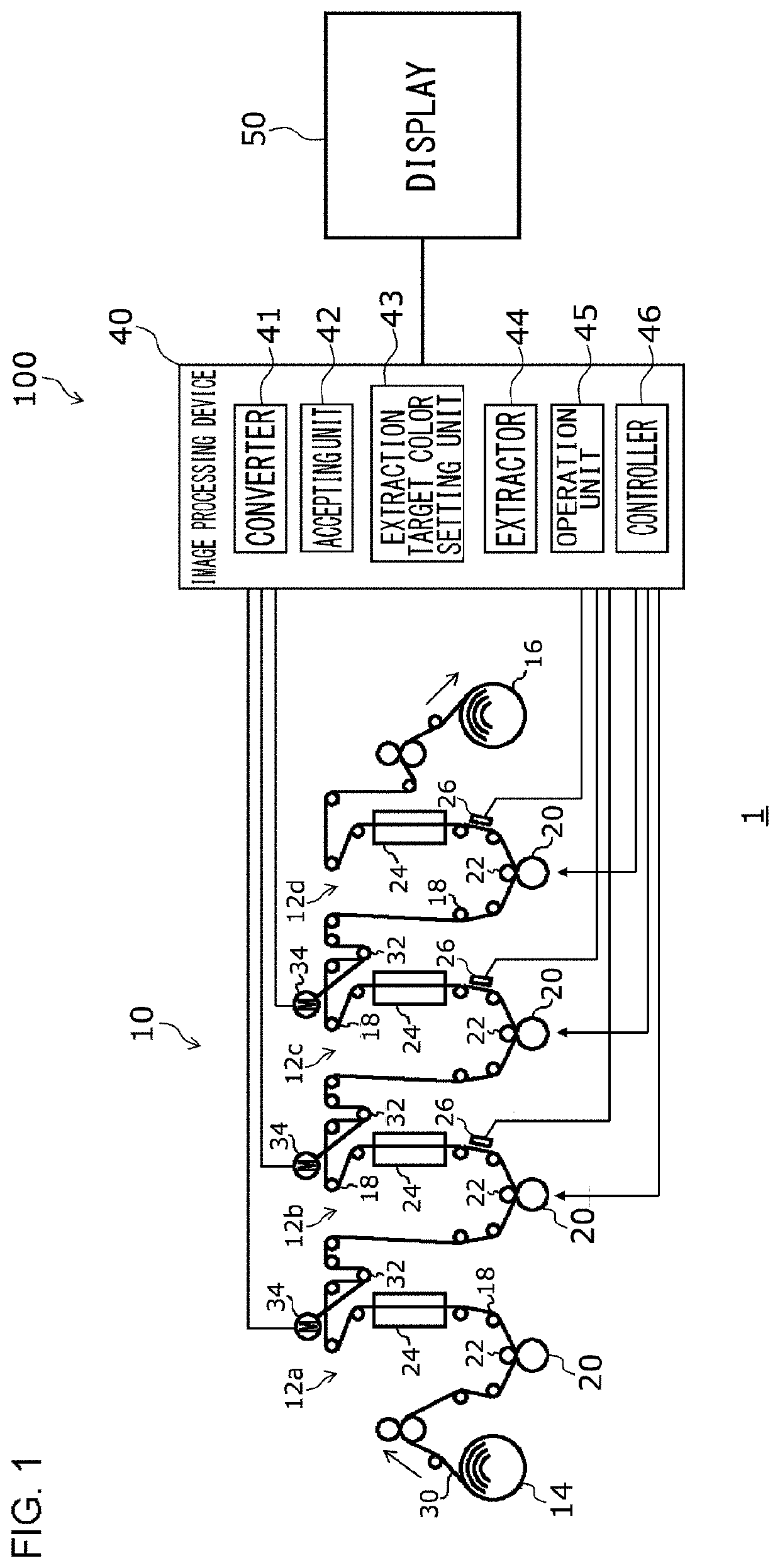
[0025]FIG. 1 is a view illustrating a print system 1 according to the first embodiment. As illustrated in FIG. 1, the print system 1 includes a printing press 10 and a control device 100. The printing press 10 is a multicolor gravure rotary printing press which enables four-color printing on a web 30 which is a target printed material. The printing press 10 includes a first print unit 12a, a second print unit 12b, a third print unit 12c, a fourth print unit 12d, an unwinder 14, a winder 16, a plurality of compensator rollers 32 and a plurality of register motors 34.
[0026]The four first print unit 12a, second print unit 12b, third print unit 12c and fourth print unit 12d are disposed in series. In addition, the first print unit 12a, the second print unit 12b, the third print unit 12c and the fourth print unit 12d will be collectively referred to as a “print unit 12” as appropriate.
[0027]At an upstream of the first print unit 12a, the unwinder 14 which supplies the web 30 to be printe...
second embodiment
[0074]The second embodiment differs from the first embodiment in controlling a printed material processing device based on an image processing technique according to the first embodiment. Differences from the first embodiment will be mainly described below.
[0075]FIG. 10 is a view illustrating a printed material processing system 2 according to the second embodiment. As illustrated in FIG. 10, the printed material processing system 2 includes a printed material processing device 80 and a control device 100A. The printed material processing device 80 processes a printed material. The printed material processing device 80 is, for example, a cutter which cuts the printed material.
[0076]The control device 100A controls the printed material processing device 80. A capturing unit 26 of the control device 100A captures a cut mark or a slitter mark as an inspection target object printed on the printed material. In an image processing device 40A of the control device 100A, a controller 46A co...
third embodiment
[0079]The third embodiment differs from the first embodiment in inspecting a printed material based on an image processing technique according to the first embodiment. Differences from the first embodiment will be mainly described below.
[0080]FIG. 11 is a view illustrating an inspection system 3 according to the third embodiment. As illustrated in FIG. 11, the inspection system 3 includes a rewind inspection machine 90 and an inspection device 400. The rewind inspection machine 90 rewinds a roll-shaped printed material. The inspection device 400 is attached to the rewind inspection machine 90 and inspects the printed material. The inspection device 400 includes a capturing unit 26, an image processing device 40B and a display 50. The capturing unit 26 captures a pattern as the inspection target object printed on the printed material.
[0081]The image processing device 40B differs from the first embodiment in including a comparator 47 in place of a controller 46. The comparator 47 comp...
PUM
 Abstract
Description
Claims
Application Information
 - R&D
- Intellectual Property
- Life Sciences
- Materials
- Tech Scout
- Unparalleled Data Quality
- Higher Quality Content
- 60% Fewer Hallucinations
Browse by: Latest US Patents, China's latest patents, Technical Efficacy Thesaurus, Application Domain, Technology Topic, Popular Technical Reports.
© 2025 PatSnap. All rights reserved.Legal|Privacy policy|Modern Slavery Act Transparency Statement|Sitemap|About US| Contact US: help@patsnap.com