Chemical mechanical polishing apparatus

a mechanical and polishing technology, applied in the direction of electric devices, lapping tools, polishing compositions with abrasives, etc., can solve the problems of reducing productivity and work efficiency, difficult to optimize the polishing efficiency of a substrate, and difficult to modify the surface of the polishing pad under the optimum conditions, so as to improve process efficiency and polishing efficiency, improve process efficiency and improve polishing efficiency

Active Publication Date: 2020-09-22
K C TECH
View PDF16 Cites 0 Cited by
  • Summary
  • Abstract
  • Description
  • Claims
  • Application Information

AI Technical Summary

Benefits of technology

[0031]As described above, according to an embodiment of the present invention, the process efficiency can be improved and the polishing efficiency can be improved.
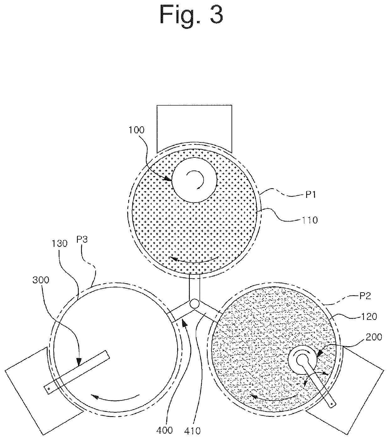
[0032]Particularly, according to an embodiment of the present invention, it is possible to perform different processes at different process positions using a plurality of polishing platens, thereby improving the process efficiency and polishing efficiency.
[0033]Also, according to an embodiment of the present invention, since different polishing processes can be performed at different process positions using a plurality of polishing platens, different processes can be simultaneously performed. Accordingly, productivity can be improved, and efficiency deterioration and performance deterioration caused when different processes are performed in a single polishing pad can be prevented.
[0034]In addition, according to an embodiment of the present invention, while a chemical mechanical polishing process is being performed on a specific polishing pad, the surface modification process can be sufficiently and stably performed in another polishing pad. Since the chemical mechanical polishing process for another substrate used in the next polishing process can be performed on another polishing pad that is optimally modified, the polishing quality and polishing uniformity of the substrate can be further improved.
[0035]Furthermore, according to an embodiment of the present invention, since a chemical mechanical polishing process can be carried out using a different polishing pad without a need to modify and clean a polishing pad after the chemical mechanical polishing process is performed on the specific polishing pad, a time loss due to modification and cleaning of the polishing pad can be prevented, and a chemical mechanical polishing process for a plurality of substrates can be quickly performed.

Problems solved by technology

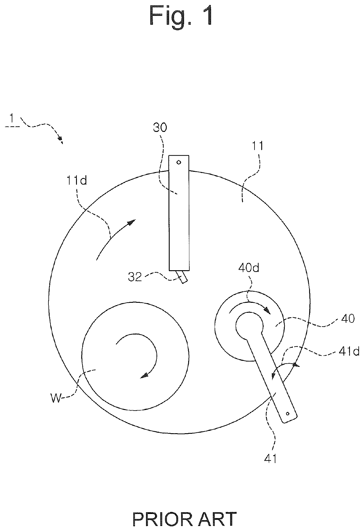
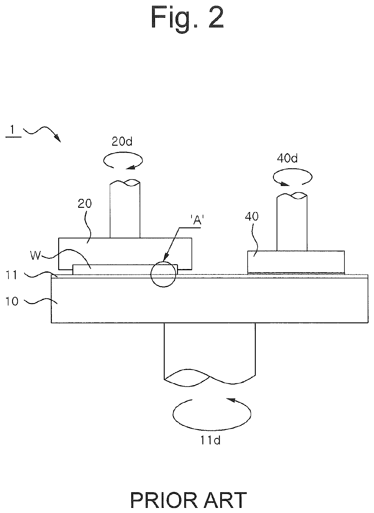
However, typically, as all of the chemical mechanical polishing process by the carrier head, the process of modifying the surface of the polishing pad by the conditioner, and the cleaning process of the polishing pad are configured to be performed on a single polishing pad, it is difficult to maximize the polishing efficiency of a substrate and to perform a quick and accurate process changeover.
However, typically, since the chemical mechanical polishing process and the surface modification process of the polishing pad are together performed on one polishing pad, it is difficult to modify the surface of the polishing pad under the optimum conditions.
Also, in the related-art, since each process is performed on one polishing pad, the chemical mechanical polishing process needs to be inevitably stopped during the cleaning process (and / or the modification process) of the polishing pad, thereby causing reduction of productivity and work efficiency.
Particularly, when a plurality of wafers are continuously processed, there is a limitation in that a time loss for changing each process of the polishing pad occurs.
For this, various studies for improving the process efficiency and the polishing efficiency are recently being conducted, but are still insufficient and more development is needed.

Method used


Image

  • Chemical mechanical polishing apparatus
  • Chemical mechanical polishing apparatus
  • Chemical mechanical polishing apparatus

Examples


Embodiment Construction

]

[0077]FIGS. 10 to 12 are views illustrating a chemical mechanical polishing apparatus according to another embodiment of the present invention. Also, the same or equivalent components as those of the above-described configuration are denoted by the same or equivalent reference numerals, and a detailed description thereof will be omitted.

[0078]Referring to FIG. 10, a chemical mechanical polishing apparatus according to another embodiment of the present invention includes a plurality of polishing platens and a polishing platen transferring unit 400′, and the polishing platen transferring unit 400′ may rotate a plurality of polishing platens 110, 120 and 130 to different process positions by moving the plurality of polishing platens 110, 120 and 130 in a straight line along a predetermined path.

[0079]The polishing platen transferring unit 400′ may straightly move the plurality of polishing platens 110, 120 and 130 using a typical rail or guide member. Hereinafter, the polishing platen...


PUM

PropertyMeasurementUnit
circumferenceaaaaaaaaaa
timeaaaaaaaaaa
densityaaaaaaaaaa

Abstract

Provided are a chemical mechanical polishing apparatus and a control method thereof. The chemical mechanical polishing apparatus includes a plurality of polishing platens provided with a polishing pad on an upper surface thereof, and a polishing platen transferring unit for transferring the plurality of polishing platens to different process positions according to a predetermined process sequence. Here, different processes are performed at different process positions.

Description

CROSS-REFERENCE TO RELATED APPLICATIONS[0001]This application is a national stage of International Application No. PCT / KR2016 / 008674, filed Aug. 8, 2016, which claims benefit of priority to Korean Application No. 10-2015-0189637, filed Dec. 30, 2015, in the Korean Intellectual Property Office, the disclosures of which are incorporated herein by reference.TECHNICAL FIELD[0002]The present invention relates to a chemical mechanical polishing apparatus and a control method thereof, and more particularly, to a chemical mechanical polishing apparatus and a control method thereof capable of performing different processes at different process positions using a plurality of polishing platens.BACKGROUND ART[0003]As fine circuit lines of high density are integrated in semiconductor devices, precision polishing corresponding thereto is performed on a wafer surface. In order to more precisely perform polishing of a wafer, a Chemical Mechanical Polishing (CMP) process in which chemical polishing ...

Claims


Application Information

Patent Timeline
Patent Type & Authority Patents(United States)
IPC IPC(8): H01L21/304H01L21/67H01L21/02C09G1/02H01L21/306B24B37/20B24B37/12
CPCH01L21/02002C09G1/02H01L21/30625H01L21/304H01L21/67092B24B37/12B24B37/20
Inventor PARK, KYUNAM
Owner K C TECH
Why Eureka
Try Eureka