
Wireless device

Active Publication Date: 2020-09-22
WISTRON NEWEB
View PDF11 Cites 1 Cited by
  • Summary
  • Abstract
  • Description
  • Claims
  • Application Information

AI Technical Summary

Benefits of technology

The present disclosure is about a design that reduces interference between subsystems in a single wireless device by using two directional antennas. These antennas have high directivity, which increases the distance of wireless transmission. This design also takes advantage of the fact that the antenna performance is not affected by the main circuit board or metal barrier. The two directional antennas can be placed in different locations on the device, and connected by coaxial wires with different lengths and splitters, to create an omnidirectional pattern. Additionally, isolators are used to achieve a specific isolation performance. This design makes the wireless device more competitive, especially in cases where the device is small.

Problems solved by technology

The difficulty lies in the fact that a Wi-Fi 2.4G wireless local area network of the smart speaker needs to transmit signals for longer periods of time, which causes interference to the Bluetooth® devices operating in the same frequency band (an operating band of the Bluetooth® is about 2.4G˜2.485 GHz), so that an effective distance for playing music becomes shorter when the Bluetooth® devices are paired through the Bluetooth®.
However, the specification does not support a retransmission mechanism.
In other words, when 2.4G WiFi / Bluetooth® are used to transmit data in Time Division Duplex (TDD), once the Bluetooth® stops transmitting, an issue of audio interruption may arise.
However, null points often show in a direction along a circuit board of the conventional smart speakers, and blind spots in the horizontal plane for the pattern of the antenna cannot be eliminated.
Moreover, since the circuit board is part of the antenna, an isolation performance between the Bluetooth® and Wi-Fi is generally poor.
Moreover, considering the limitation that existing Bluetooth® chips are mostly designed with a single transceiver, it is also difficult to use multiple transceivers with multiple antennas to overcome issues relating to antenna omnidirectionality when there is a metal barrier space.

Method used


Image

  • Wireless device
  • Wireless device
  • Wireless device

Examples


Embodiment Construction

[0028]The present disclosure is more particularly described in the following examples that are intended as illustrative only since numerous modifications and variations therein will be apparent to those skilled in the art. Like numbers in the drawings indicate like components throughout the views. As used in the description herein and throughout the claims that follow, unless the context clearly dictates otherwise, the meaning of “a”, “an”, and “the” includes plural reference, and the meaning of “in” includes “in” and “on”. Titles or subtitles can be used herein for the convenience of a reader, which shall have no influence on the scope of the present disclosure.

[0029]The terms used herein generally have their ordinary meanings in the art. In the case of conflict, the present document, including any definitions given herein, will prevail. The same thing can be expressed in more than one way. Alternative language and synonyms can be used for any term(s) discussed herein, and no speci...


PUM


Abstract

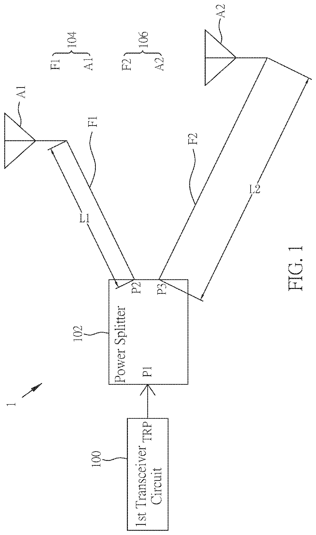
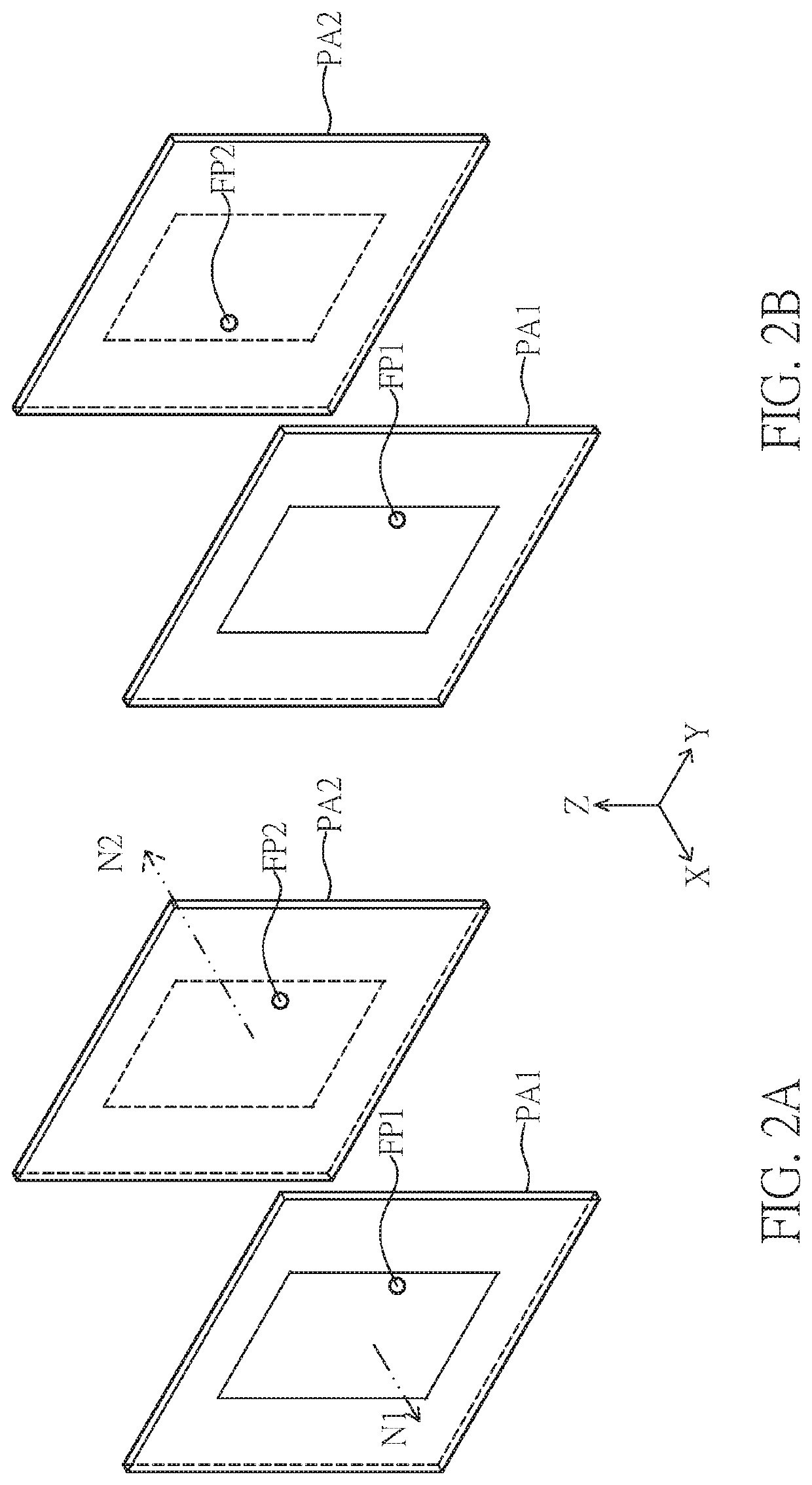
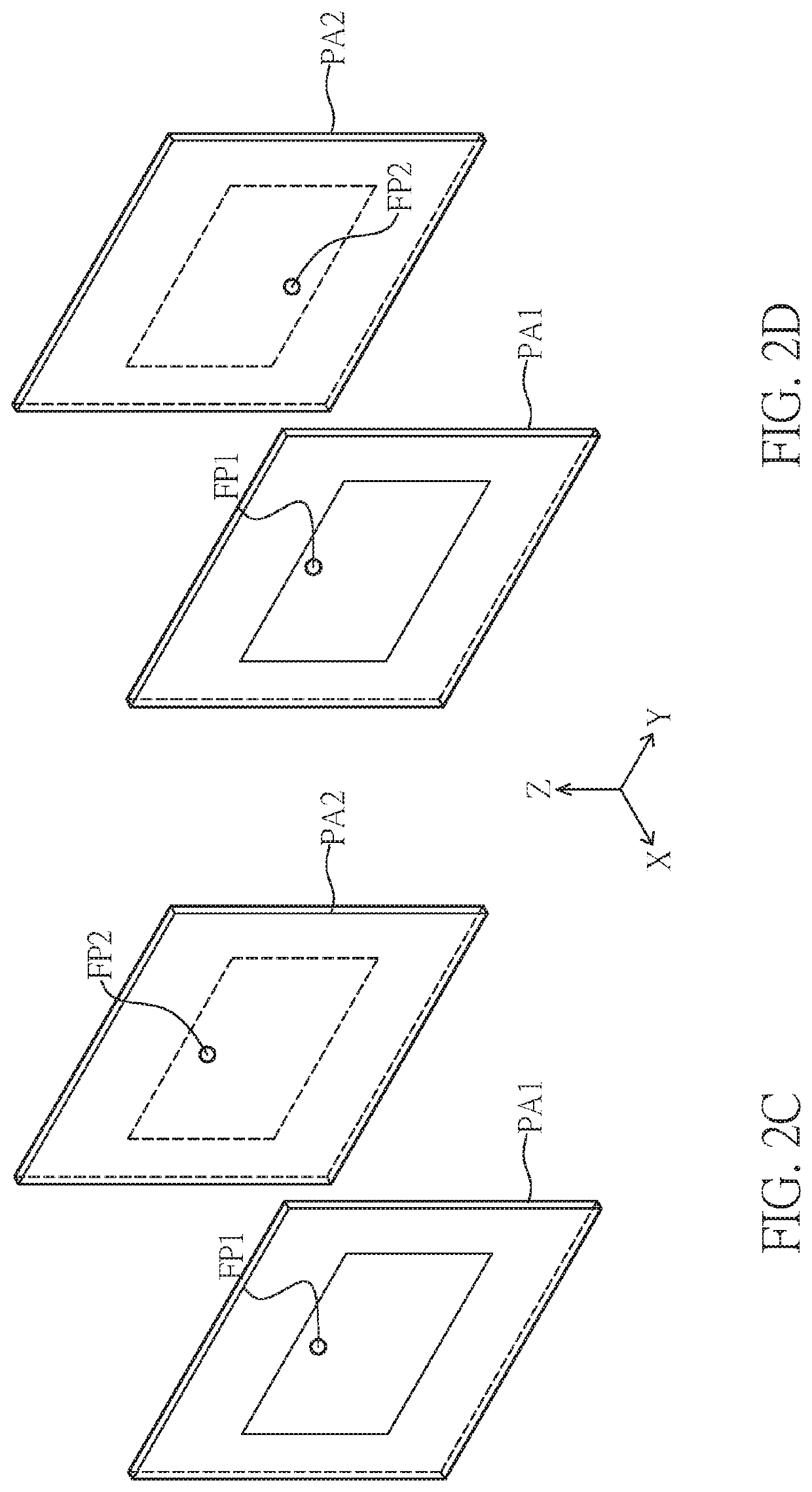
A wireless device includes a first transceiver circuit, a power splitter, a first directional antenna, and a second directional antenna. The first directional antenna is connected to a second end of the power splitter and has a first feeding portion and a first radiation unit, and the first feeding portion has a first line length. The second directional antenna is connected to a third end of the power splitter and has a second feeding portion and a second radiation unit, and the second feeding portion has a second line length. A phase difference is provided between the first directional antenna and the second directional antenna. The first transceiver circuit forms, through the first directional antenna, the second directional antenna and the predetermined phase difference, a predetermined pattern to transmit or receive signals, and the predetermined pattern has omnidirectionality.

Description

CROSS-REFERENCE TO RELATED PATENT APPLICATION[0001]This application claims the benefit of priority to Taiwan Patent Application No. 108110698, filed on Mar. 27, 2019. The entire content of the above identified application is incorporated herein by reference.[0002]Some references, which may include patents, patent applications and various publications, may be cited and discussed in the description of this disclosure. The citation and / or discussion of such references is provided merely to clarify the description of the present disclosure and is not an admission that any such reference is “prior art” to the disclosure described herein. All references cited and discussed in this specification are incorporated herein by reference in their entireties and to the same extent as if each reference was individually incorporated by reference.FIELD OF THE DISCLOSURE[0003]The present disclosure relates to a wireless device, and more particularly to a wireless device capable of providing an omnidi...

Claims


Application Information

Patent Timeline
IPC IPC(8): H01Q1/24H01Q25/00H01Q1/52
CPCH01Q25/005H01Q1/525H01Q1/243H01Q21/28H01Q9/16H01Q9/0407H01Q1/2291H01Q5/35H01Q1/521
Inventor CHANG, JUI-CHIHCHEN, WEI-KAICHANG, YU-HSIANG
Owner WISTRON NEWEB
Features
  • Generate Ideas
  • Intellectual Property
  • Life Sciences
  • Materials
  • Tech Scout
  • Unparalleled Data Quality
  • Higher Quality Content
  • 60% Fewer Hallucinations
Learn More