
Multi-purpose coolant interface

a coolant interface and multi-purpose technology, applied in the direction of electrical apparatus construction details, instruments, particular array feeding systems, etc., can solve the problem that the next-generation radar power level exceeds the capability of cost-effective conduction cooling methods, and achieve the effect of increasing and maintaining seal compression

Active Publication Date: 2020-09-29
RAYTHEON CO
View PDF6 Cites 4 Cited by
  • Summary
  • Abstract
  • Description
  • Claims
  • Application Information

AI Technical Summary

Benefits of technology

The solution enables higher power levels and increased reliability of electronics by providing effective liquid cooling with minimized leaks, even under extreme conditions, allowing for higher performance without the limitations of traditional conduction cooling.

Problems solved by technology

However, next-generation radar power levels exceed the capability of cost effective conduction cooling methods and require liquid cooled line replaceable units (LRUs) to support increased radio frequency (RF) performance while providing high reliability electronics.

Method used


Image

  • Multi-purpose coolant interface
  • Multi-purpose coolant interface
  • Multi-purpose coolant interface

Examples


Embodiment Construction

[0012]It should be understood at the outset that, although exemplary embodiments are illustrated in the figures and described below, the principles of the present disclosure may be implemented using any number of techniques, whether currently known or not. The present disclosure should in no way be limited to the exemplary implementations and techniques illustrated in the drawings and described below. Additionally, unless otherwise specifically noted, articles depicted in the drawings are not necessarily drawn to scale.

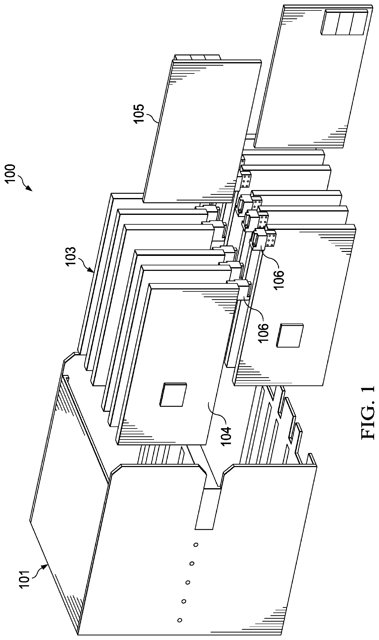
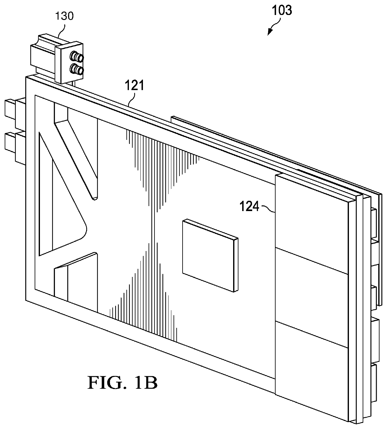
[0013]In conventional conduction cooled electronics assemblies, each LRU is conduction cooled by a liquid-cooled heatsink, typically via an edge connection. Increasing operating power above existing levels may push the electronics beyond acceptable operating temperatures. Liquid cooling of the individual assemblies could allow increased operating power. In addition, the cost effective limits of conduction cooling appear to have been reached and are beginning to hinder...


PUM


Abstract

A coolant interface includes a line replaceable unit (LRU) inserted into a slot within a modular assembly such as a chassis for an electronics assembly. Quick disconnect fluid coupling fittings on the LRU mate with counterpart fittings on a fluid distribution manifold within the chassis when the LRU is inserted into the slot. A seal surrounding the quick disconnect fluid coupling fittings on a flat surface abutting a counterpart surface on the fluid distribution manifold when the LRU is inserted into the slot compresses the seal against the counterpart surface. Alignment pin(s) projecting from the flat surface and received by corresponding guide holes within the counterpart surface, and captive hardware provides pressure between the flat surface and the counterpart surface to increase and maintain compression of the seal. The alignment pins and captive hardware are arranged to increase mechanical stability of the connection.

Description

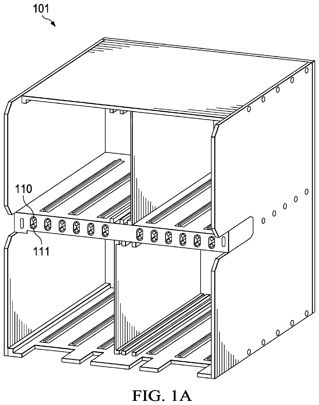
TECHNICAL FIELD[0001]The present disclosure is directed in general to cooling large radar arrays and, more particularly, to improving a coolant interface for such arrays.BACKGROUND OF THE DISCLOSURE[0002]Customers are seeking higher power radars to keep pace with increasingly sophisticated threats. However, next-generation radar power levels exceed the capability of cost effective conduction cooling methods and require liquid cooled line replaceable units (LRUs) to support increased radio frequency (RF) performance while providing high reliability electronics.SUMMARY OF THE DISCLOSURE[0003]In one embodiment of the disclosure, a coolant interface includes a line replaceable unit configured to be inserted into a slot within a modular assembly such as a chassis for a radar module assembly or a computer. The line replaceable unit includes quick disconnect fluid coupling fittings configured to mate with counterpart fittings on a fluid distribution manifold within a chassis for the modula...

Claims


Application Information

Patent Timeline
Patent Type & Authority Patents(United States)
IPC IPC(8): H05K7/20G01S7/03H01Q21/00H01R13/73
CPCH01Q21/0025H01R13/73H05K7/20763G01S7/032H05K7/20645H05K7/20272G01S7/03
Inventor MCCORDIC, CRAIG H.ELLSWORTH, JOSEPH R.SOUTHARD, TODDMORIONDO, DOUGLAS
Owner RAYTHEON CO
Learn More