Device and method for uniform far-field illumination with LEDs

a technology of leds and devices, applied in the direction of lighting support devices, distance measurement, instruments, etc., can solve the problems of light intensity loss that is usually observed, and achieve the effect of simplifying manufacturing processes and the weight of the light sour

Active Publication Date: 2020-10-13
TERABEE
View PDF18 Cites 0 Cited by
  • Summary
  • Abstract
  • Description
  • Claims
  • Application Information

AI Technical Summary

Benefits of technology

[0010]The elimination of the need for external optics significantly simplifies manufacturing processes and the weight of the light source.

Problems solved by technology

However, due to the use of optics, light intensity losses are usually observed.

Method used


Image

  • Device and method for uniform far-field illumination with LEDs
  • Device and method for uniform far-field illumination with LEDs
  • Device and method for uniform far-field illumination with LEDs

Examples


Embodiment Construction

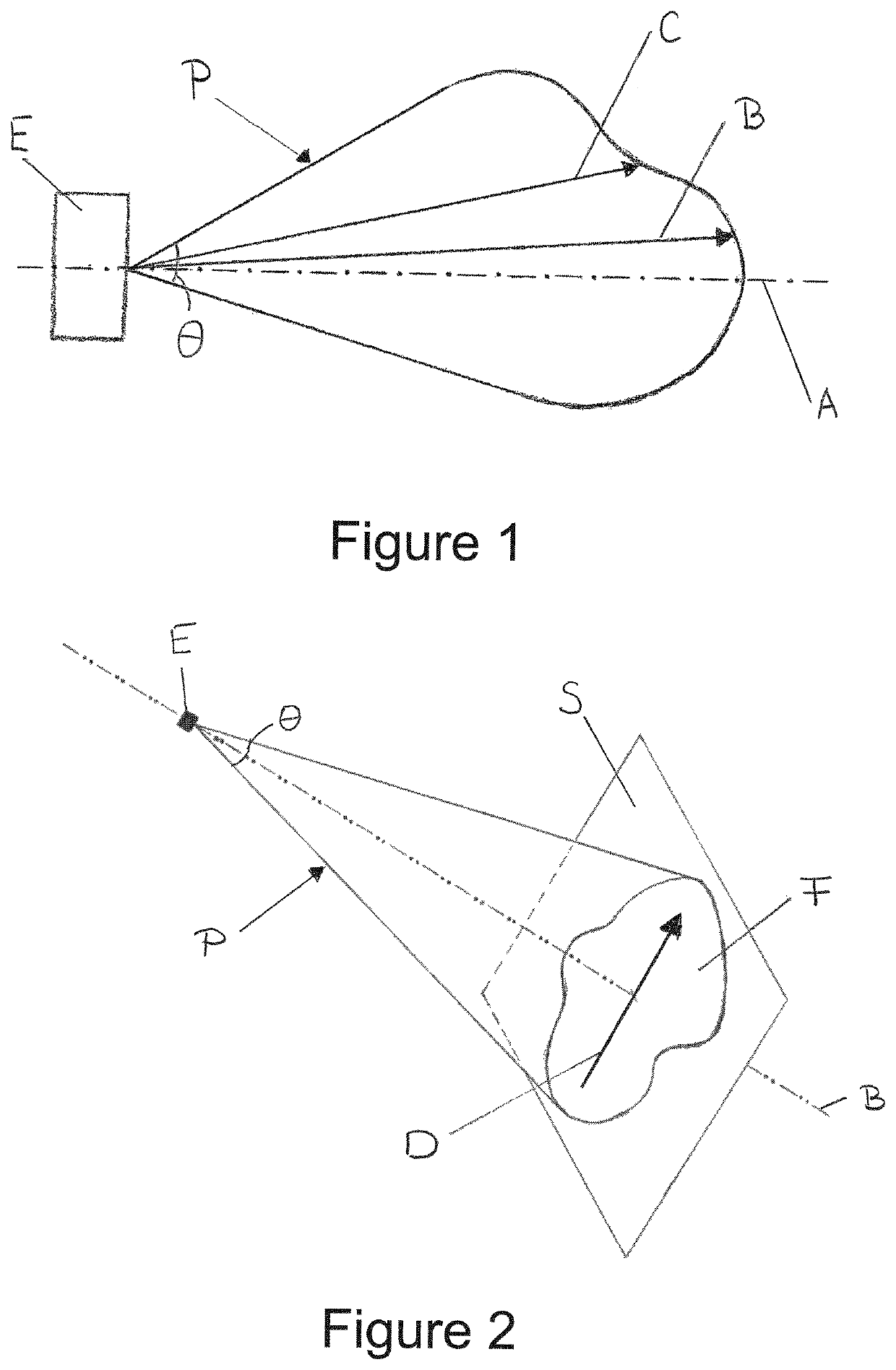
[0036]In order to better understand the invention, a specific physical property of a LED which has a significant influence on non-uniformities in the far field illumination needs to be presented: the spatial radiation characteristics.

[0037]It is well known that each LED has a specific spatial radiation. Spatial radiation can be described through a pattern of relative light strength in any direction from the light source.

[0038]LED spatial radiation has been studied and has shown that spatial radiation repartition is either lambertian or non-lambertian. A specific spatial radiation repartition generates a specific irradiance distribution pattern on a selected surface to be illuminated. Many different irradiance distribution patterns have been observed: bat wings, parabolic, hemispherical shapes among others. For a given chemical composition and geometry of the semiconductor, chip spatial radiation and related irradiance distribution patterns can be simulated.

[0039]In addition, several...


PUM

PropertyMeasurementUnit
angleaaaaaaaaaa
opening anglesaaaaaaaaaa
angleaaaaaaaaaa

Abstract

A light source for illuminating a selected surface, the light source comprising a plurality of Light Emitting Diodes (LED) mounted on a substrate; each of the plurality of LEDs having an optical axis and generating a radiation pattern propagating along the optical axis. The plurality of LEDs are arranged so that each optical axis is oriented substantially towards a determined far-field central point; and the plurality of LEDs provide a predetermined irradiance distribution on the selected surface. Each of the radiation patterns defines a preferential direction; and each of the plurality of LEDs is arranged so that the preferential direction of each of the plurality of LEDs is unique.

Description

CROSS REFERENCE TO RELATED APPLICATIONS[0001]The present application is a United States national stage application of International patent application PCT / EP2016 / 060998 filed on May 17, 2016 designating the United States, and claims foreign priority to European patent application EP 15305739.3 filed on May 18, 2015, the contents of both documents being herewith incorporated by reference in their entirety.TECHNICAL FIELD[0002]The present invention relates to the field of Light Emitting Diode (LED) lighting, and more particularly to uniform field illumination by LEDs. In particular the invention is directed to LED light sources for use in the field of Time of Flight cameras and / or 3D cameras.PRIOR ART[0003]A LED is a wide band non-coherent light source. Due to the simple LED structure, easy modulation, and good reliability, LEDs are widely used in various technical fields.[0004]However, LEDs do not always approximate well as a point source of light giving a spherical light distributio...

Claims


Application Information

Patent Timeline
Patent Type & Authority Patents(United States)
IPC IPC(8): G01C3/08G01S7/481G01S17/89F21K9/00G01S17/42F21V21/00F21Y103/10F21Y105/12F21Y105/16F21Y105/18F21Y115/10G01S17/894
CPCF21K9/00G01S7/4815G01S17/89G01S17/42F21Y2115/10F21Y2105/12F21Y2103/10F21V21/00F21Y2105/18F21Y2105/16G01S17/894
Inventor RUFFO, MASSIMILIANOKOVERMANN, JAN W
Owner TERABEE
Why Eureka
Try Eureka