Fan structure

a technology of fan structure and fan blade, which is applied in the direction of machines/engines, rotary propellers, liquid fuel engines, etc., can solve the problems of overheating of electronic products, high heat generation of internal components of electronic products, and loud noise of entire fans, so as to reduce noise, reduce the strength of the vortex, and reduce the noise

Active Publication Date: 2020-10-20
ASIA VITAL COMPONENTS SHENZHEN CO LTD
View PDF13 Cites 0 Cited by
  • Summary
  • Abstract
  • Description
  • Claims
  • Application Information

AI Technical Summary

Benefits of technology

[0008]It is therefore a primary object of the present invention to provide a fan structure, which can destroy the production of the vortex of the blade of the conventional fan.
[0009]It is a further object of the present invention to provide the above fan structure, which can greatly minify the strength of the vortex of the blade of the conventional fan.
[0010]It is still a further object of the present invention to provide the above fan structure, which can change the structure of the sound field of the vortex so as to lower the noise of the entire fan structure.
[0013]According to the structural design of the present invention, by means of the protrusion section formed on the end edge of the blade, according to Bernoulli's principle, when the fan structure operates, the airflow pressure under the lower surface is higher than the airflow pressure on the upper surface. Therefore, the airflow will upward turn over and flow from the lower surface to the upper surface. Due to the pressure difference between the upper and lower surfaces, a vortex will be produced. At this time, the structure of the protrusion section will destroy the production of the large vortex of the blade of the conventional fan. In other words, by means of the structure of the protrusion section, the strength of the vortex will be greatly minified to form smaller vortex. The interaction between the vortex and the frame body is one of the sources of the noise of the fan structure. Therefore, the large vortex is destroyed by the protrusion section to form small vortex so that the strength of the vortex is weakened. As a result, the interaction between the vortex and the frame body is weakened to lower the noise. The structure of the sound field of the vortex is changed so that the noise of the entire fan structure is greatly lowered.

Problems solved by technology

In operation, the internal components of the electronic products (such as computers and notebooks) will generate high heat.
Otherwise, the electronic product will overheat.
1. A larger vortex is produced.
2. The entire fan will make loud noise.

Method used


Image

  • Fan structure
  • Fan structure
  • Fan structure

Examples


Embodiment Construction

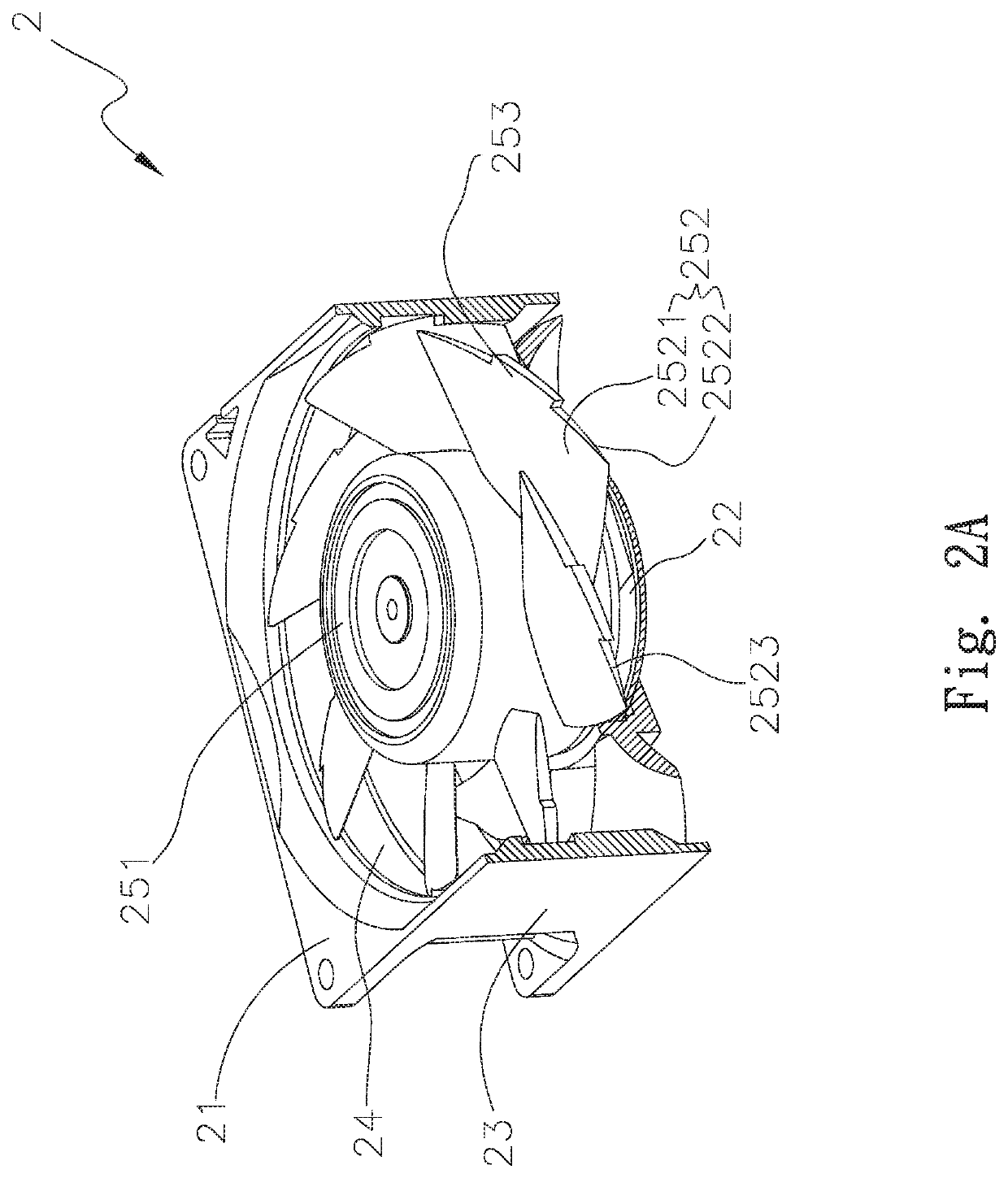
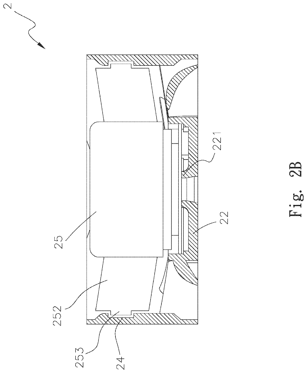
[0032]Please refer to FIGS. 2A, 2B, 2C and 2D. FIG. 2A is a perspective sectional view of a first embodiment of the fan structure of the present invention. FIG. 2B is a sectional view of the first embodiment of the fan structure of the present invention. FIG. 2C is a sectional view of the first embodiment of the fan structure of the present invention, showing the change of the sound field of the noise. FIG. 2D is a top view of the first embodiment of the fan structure of the present invention. According to the first embodiment, the fan structure 2 of the present invention includes a frame body 21 and a fan impeller 25. The frame body 21 has a base seat 22 and an annular wall 23. A bearing cup 221 upward extends from the center of the base seat 22. At least one groove 24 is formed on inner wall face of the annular wall 23. In this embodiment, the groove 24 is annularly integrally formed on the inner wall face of the annular wall 23 by injection molding.

[0033]The fan impeller 25 is co...


PUM


Abstract

A fan structure includes a frame body and a fan impeller. The frame body has a base seat and an annular wall. A bearing cup upward extends from a center of the base seat. At least one groove is annularly formed on inner wall face of the annular wall. The fan impeller is pivotally disposed in the bearing cup and has a hub and multiple blades outward extending from the hub. Each blade has an end edge. At least one protrusion section outward protrudes from the end edge into the groove. According to the design of the fan structure, the protrusion section can destroy the production of the vortex of the blade of the conventional fan so as to greatly minify the strength of the vortex. Therefore, the structure of the sound field of the vortex is changed so that the noise of the fan structure is lowered.

Description

BACKGROUND OF THE INVENTION1. Field of the Invention[0001]The present invention relates generally to a fan structure, and more particularly to a fan structure, which can destroy the production of the vortex of the blade of the conventional fan so as to greatly minify the strength of the vortex. Therefore, the structure of the sound field of the vortex is changed so that the noise of the fan structure is lowered.2. Description of the Related Art[0002]Along with the continuous advance of science and technologies, the dependence of peoples on various electronic apparatuses has more and more increased. In operation, the internal components of the electronic products (such as computers and notebooks) will generate high heat. The heat generated by the internal components must be conducted outside the electronic product in time. Otherwise, the electronic product will overheat. In general, a fan is disposed in the electronic product to dissipate the heat and keep the electronic product oper...

Claims


Application Information

Patent Timeline
Patent Type & Authority Patents(United States)
IPC IPC(8): B63H1/26F04D29/66F04D29/52F04D25/08F04D29/38H01L23/467
CPCF04D29/384F04D29/526F04D29/663F04D25/08H01L23/467F04D29/522F05D2260/96F05B2260/96
Inventor CHANG, BOR-HAWCHEN, YU-TZUWANG, CHUNG-SHU
Owner ASIA VITAL COMPONENTS SHENZHEN CO LTD
Why Eureka
Try Eureka