A diversion structure for ventilation and air supply facilities in open flow flood discharge tunnels

A technology for flood discharge tunnels and facilities, applied in marine engineering, construction, barrage/weir, etc., can solve the problems of small air volume, increased engineering volume, strong noise, etc., and achieve a good working environment, low engineering cost, and noise reduction. Effect

A technology for flood discharge tunnels and facilities, applied in marine engineering, construction, barrage/weir, etc., can solve the problems of small air volume, increased engineering volume, strong noise, etc., and achieve a good working environment, low engineering cost, and noise reduction. Effect

CN109371928BActive Publication Date: 2020-05-08SICHUAN UNIV +2

Image

  • A diversion structure for ventilation and air supply facilities in open flow flood discharge tunnels
  • A diversion structure for ventilation and air supply facilities in open flow flood discharge tunnels
  • A diversion structure for ventilation and air supply facilities in open flow flood discharge tunnels

Examples


Embodiment 1

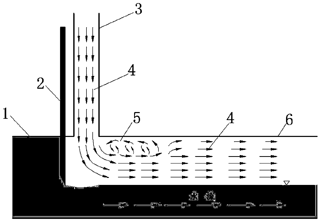
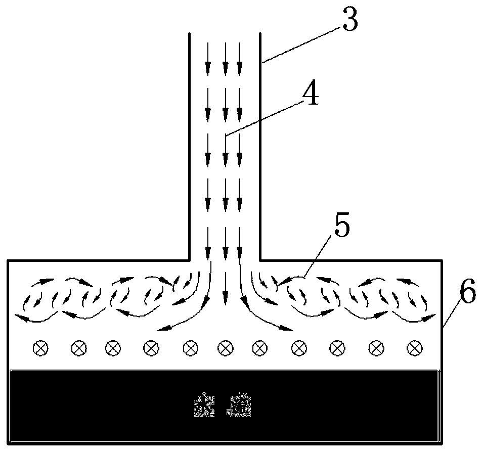
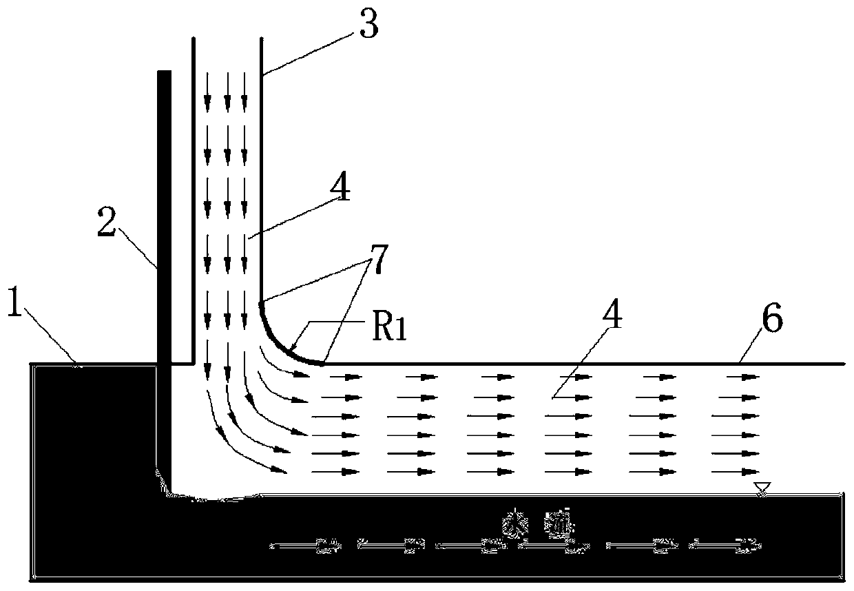
[0025] The diversion structure of the ventilation and air supply facilities of the open flow flood discharge tunnel described in this embodiment is constituted as attached image 3 , Figure 5-4shown. The length of open flow flood discharge tunnel 6 is 200 meters, the width is 10 meters, and the flow velocity of the flood discharge is 30m / s. The ventilation and air supply well of ventilation and air supply facility 3 is set at the beginning position of the open flow flood discharge tunnel behind the flood discharge gate 2, and the ventilation and air supply well is vertical. In the open flow flood discharge tunnel, the axis of the ventilation and air supply well is connected with the axis of the open flow flood discharge tunnel. Between the holes, a 1 / 4 arc diversion sill 7 is connected in the direction of the water flow and on both sides, and a right-angle diversion sill is connected in the counterflow direction, and the diversion sill in the direction of the water flow and ...

Embodiment 2

[0027] The diversion structure of the ventilation and air supply facilities of the open flow flood discharge tunnel described in this embodiment is constituted as attached Figure 4 , Figure 5-5 shown. The length of open flow flood discharge tunnel 6 is 200 meters, the width is 10 meters, and the flow velocity of the flood discharge is 30m / s. The ventilation and air supply well of ventilation and air supply facility 3 is set at the beginning position of the open flow flood discharge tunnel behind the flood discharge gate 2, and the ventilation and air supply well is vertical. In the open flow flood discharge tunnel, the axis of the ventilation well is connected with the open flow flood discharge tunnel axis, and its cross-sectional area is a circle with a radius of 2 meters. The ventilation well and the open flow flood discharge tunnel are connected by an arc diversion sill 7. The arc diversion sill is 1 / 4 arc diversion sill in different directions, and the arc radius R of t...


PUM


Abstract

The invention discloses a flow guide structure of a ventilating and air supplementing facility of an open flow flood discharge tunnel. An arc flow guide ridge (7) used for guiding air flow to enter the open flow flood discharge tunnel is arranged at the connecting part between a ventilating and air supplementing facility and the open flow flood discharge tunnel (6), the arc length of the arc flowguide ridge is one fourth arc, and the radius of the arc is determined according to the maximum wind speed in the ventilating and air supplementing facility under the maximum flood discharge flow. Theventilating and air supplementing facility and the open flow flood discharge tunnel (6) are connected through the arc flow guide ridge, the flow direction of the air flow at the connecting part between the ventilating and air supplementing facility and the open flow flood discharge tunnel under the condition of high ventilation and wind speed can be smoothed, local position airflow vortexes are eliminated, the ventilating and air supplementing effects of the ventilating and air supplementing facility are improved, and strong noise generated due to the fact that the local air flows in an adverse flow state is avoided, the operation safety of the flood discharge tunnel of the water conservancy project and the production and living environment of workers are guaranteed.

Description

technical field [0001] The invention belongs to the technical field of flood discharge tunnels in water conservancy and hydropower projects, and in particular relates to a ventilation and air supply facility for open flow flood discharge tunnels. Background technique [0002] In order to meet the needs of flood discharge and emptying projects, large-scale water conservancy projects often need to build discharge structures such as flood discharge tunnels and emptying tunnels. Different from the traditional spillway, the tunnel-type open flow flood discharge tunnel is not directly connected with the atmosphere, so it is often necessary to use ventilation and air supply facilities such as ventilation wells and ventilation air supply tunnels installed at the entrance of the open flow flood discharge tunnel to supplement air into the open flow flood discharge tunnel. If the amount of air supplemented by the ventilation and air supply facilities cannot reach the required air volum...

Claims


Application Information

Patent Timeline
08 May 2020
Publication
CN109371928B
IPC
E02B8/06
CPC
E02B8/06
Inventors
邓军; 卫望汝