Wingtip device for aircraft wing

A wing and wing tip technology, which is applied to the wing tip device field of the main wing of an aircraft, can solve the problem that the shape design of the sail does not consider the sweep angle and the skimming angle, and does not consider the fusion of the wing tip sail and the wing. The general drag reduction effect of tip sails can achieve the effect of increasing lift, reducing drag, and weakening shock wave intensity.

Active Publication Date: 2018-11-06
COMAC +1
View PDF4 Cites 0 Cited by
  • Summary
  • Abstract
  • Description
  • Claims
  • Application Information

AI Technical Summary

Problems solved by technology

However, in the design of the traditional wingtip blade and wingtip device, the fusion of the wingtip blade and the wing is not considered, and the wingtip blade is only "inserted" on the wing tip; moreover, the sail is not After aerodynamic design, it is just a simple flat plate, and there is no airfoil design for the sail; the sweep angle and skimmer problem are not considered in the shape design of the sail
Due to the general drag reduction effect of traditional wingtip sails, this kind of wingtip device is not very suitable for modern civil aircraft

Method used


Image

  • Wingtip device for aircraft wing
  • Wingtip device for aircraft wing
  • Wingtip device for aircraft wing

Examples


Embodiment Construction

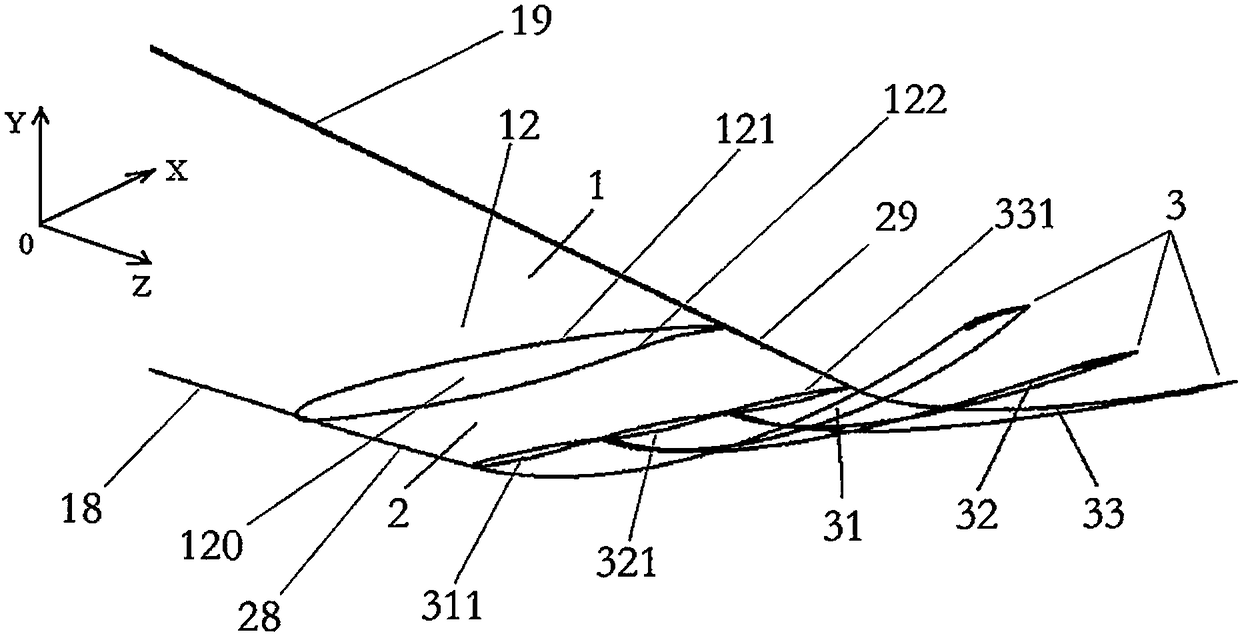
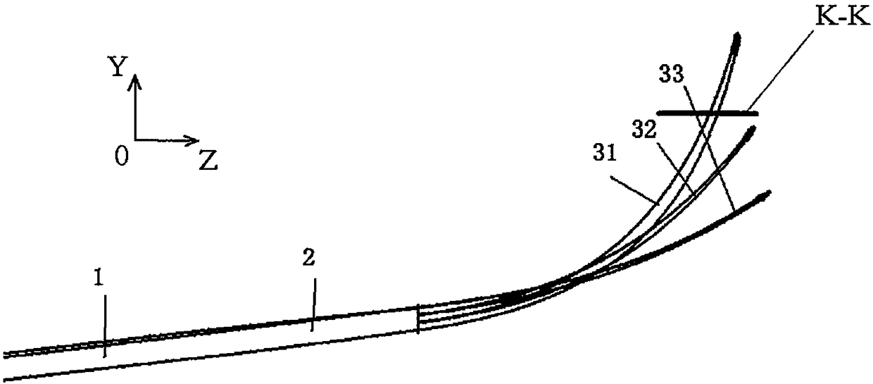
[0041] The present invention will be described in further detail below in conjunction with the accompanying drawings and specific examples. For the convenience of the discussion, "up", "down", "left", and "right" are used to indicate the directions in each schematic diagram, which is conducive to the development of the discussion. According to the characteristics of the present invention, the specific implementation method is in figure 2 The XYZ coordinate system is shown in , and the XOY plane view, YOZ plane view, and ZOX plane view are used in some of the subsequent drawings. When reading these drawings, you can combine figure 2 The three-dimensional diagram in is understood.

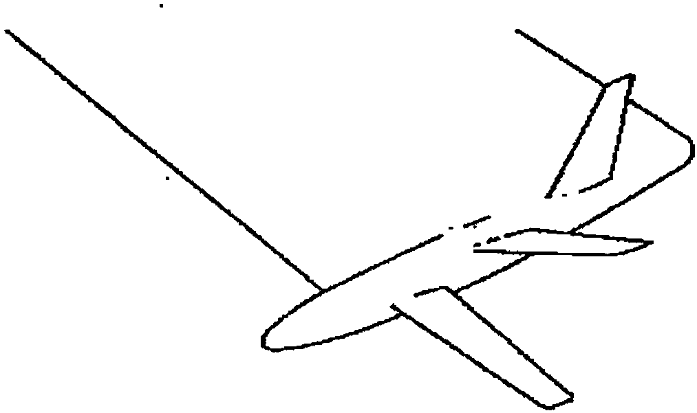
[0042] Such as figure 2 Shown is the preferred embodiment of the wingtip device of the aircraft wing of the present invention, in particular, the preferred embodiment of the wingtip device of the main wing of the aircraft. Nevertheless, those skilled in the art can understand that the technical...


PUM


Abstract

The invention provides wingtip devices of airplane wings. The wingtip devices are symmetrically arranged on wingtip portions of the wings on the two sides of an airplane. At least two wingtip sails are arranged on the outer side of the wingtip portion of the wing on each side. A wingtip sail root of each wingtip sail is in smooth connection with the outer end face of the wingtip portion of the corresponding wing in the length direction of the wing. Each wingtip sail upwards bends and tilts in the length direction of the corresponding wing. The wingtip sail root of each wingtip sail and the outer end face of the wingtip portion of the corresponding wing are sequentially arranged in the width direction of the wing, and the wingtip sail closer to the front edge of the corresponding wing upwards bends and tilts more highly. The fusion type design is adopted, the wingtip sails are in smooth transition connection with the corresponding wings or transition zones, by fully utilizing tight arrangement of the adjacent wingtip sails, air flowing on the upper surfaces of the wingtip sails is slowed down, so that a pressure difference is obtained, and the wingtip vortex intensity is reduced accordingly.

Description

technical field [0001] The invention relates to a wingtip device of an aircraft wing, in particular to a wingtip device for an aircraft main wing. Background technique [0002] Such as figure 1 As shown in , the traditional wingtip sails are equipped with multiple sails on the wingtips, and these sails can prevent part of the wingtip airflow from forming a rotation, thereby achieving the purpose of weakening the wingtip vortex. However, in the design of the traditional wingtip blade and wingtip device, the integration of the wingtip blade and the wing is not considered, and the wingtip blade is only "inserted" on the wing tip; After aerodynamic design, it is just a simple flat plate, and there is no airfoil design for the sail blade; the sweep angle and skimmer angle are not considered in the shape design of the sail blade. Because the drag reduction effect of traditional wingtip sails is average, this kind of wingtip device is not very suitable for modern civil aircraft. ...

Claims


Application Information

Patent Timeline
Patent Type & Authority Patents(China)
IPC IPC(8): B64C3/36B64C3/28
CPCB64C3/28B64C3/36B64C23/069Y02T50/10
Inventor 钟园杨士普马超钱光平张建军陈学刚秦晓辉司江涛
Owner COMAC
Why Eureka
Try Eureka