Pumping system for generating a vacuum and method for pumping by means of this pumping system

a vacuum generation and pumping system technology, applied in the field of vacuum technology, can solve the problems of system bulkiness, increased cost and bulkiness of variable speed drive, and increased cost of variable speed drive, and achieve the effect of improving vacuum

Active Publication Date: 2020-10-20
ATELIERS BUSCH
View PDF19 Cites 2 Cited by
  • Summary
  • Abstract
  • Description
  • Claims
  • Application Information

AI Technical Summary

Benefits of technology

[0010]The present invention likewise has as object to permit a reduction of the electrical energy necessary for the evacuation of a vacuum chamber and for maintaining the vacuum as well as to achieve a decrease in the temperature of the exit gas.
[0020]Thanks to the method according to the invention, the coupling of the main claw vacuum pump and of the auxiliary pump can be carried out without requiring specific measures or apparatuses (for example sensors for pressure, temperature, current, etc.), nor servo-controls, nor data management and without calculation. Consequently the pumping system suitable for implementing the pumping method according to the present invention can comprise only a minimal number of components, can have great simplicity and can cost considerably less compared with existing systems.
[0021]Thanks to the method according to the invention, the main claw vacuum pump can operate at a single constant speed, that of the power grid, or turn at variable speeds in accordance with its own mode of operation. Consequently, the complexity and the cost of the pumping system suitable for implementing the pumping method according to the present invention can be reduced even more.
[0031]The pressure at the exit of the main claw vacuum pump becomes that at the inlet of the auxiliary vacuum pump, that of its exit always being the pressure in the conduit after the non-return valve. The more the auxiliary vacuum pump pumps, the more the pressure at the exit of the main claw vacuum pump, in the space limited by the closed non-return valve, drops and consequently the difference in pressure between the chamber and the exit of the main claw vacuum pump decreases. This slight difference reduces the internal leaks in the main claw vacuum pump and causes a reduction of the pressure in the chamber, which improves the final vacuum.
[0033]On the other hand, it is also evident that the study of the mechanical concept seeks to reduce the space between the gas discharge outlet of the main claw vacuum pump and the non-return valve with the aim of being able to lower the pressure there more quickly.

Problems solved by technology

Also speed variation by variable speed drive entails additional costs and more bulkiness.
This solution requires numerous parts and presents problems of reliability.
This type of systems is bulky, operates either with by-pass valves presenting problems of reliability or by employing means of measurement, control, adjustment or servo-control.
However, these means of control, adjustment or servo-control must be controlled in an active way, which necessarily results in an increase in the number of components of the system, its complexity and its cost.

Method used


Image

  • Pumping system for generating a vacuum and method for pumping by means of this pumping system
  • Pumping system for generating a vacuum and method for pumping by means of this pumping system

Examples


first embodiment

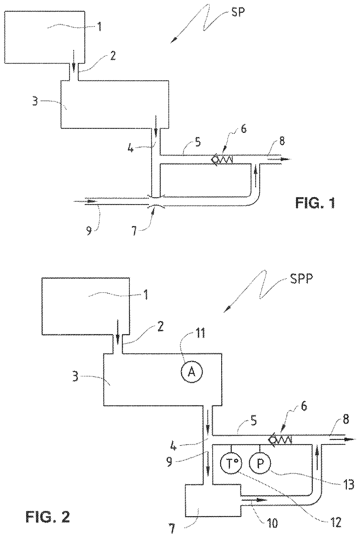
[0039]FIG. 1 represents a pumping system SP for generating a vacuum, which is suitable for implementing a pumping method according to the present invention.

[0040]This pumping system SP comprises a chamber 1, which is connected to the suction end 2 of a main vacuum pump constituted by a claw pump 3. The gas discharge outlet of the main claw vacuum pump 3 is connected to an evacuation conduit 5. A non-return discharge valve 6 is placed in the evacuation conduit 5, which, after this non-return valve, continues into the gas exit conduit 8. The non-return valve 6, when it is closed, permits the formation of a volume 4, contained between the gas discharge outlet of the main vacuum pump 3 and itself.

[0041]The pumping system SP also comprises the auxiliary vacuum pump 7, connected in parallel to the non-return valve 6. The suction end of the auxiliary vacuum pump is connected to the space 4 of the evacuation conduit 5 and its discharge end is connected to the conduit 8.

[0042]Already with th...


PUM


Abstract

The present invention relates to a pumping system to generate a vacuum (SP), comprising a main vacuum pump which is a claw pump (3) having a gas suction inlet (2) connected to a vacuum chamber (1) and a gas discharge outlet (4) leading into a gas evacuation conduit (5) in the direction of a gas exhaust outlet (8) outside the pumping system. The pumping system comprises a non-return valve (6) positioned between the gas discharge outlet (4) and the gas exhaust outlet (8), and an auxiliary vacuum pump (7) connected in parallel to the non-return valve. In a pumping method by means of this pumping system (SP), the main vacuum pump (3) is started up in order to pump the gases contained in the vacuum chamber (1) and to discharge these gases through its gas discharge outlet (4), simultaneously to which the auxiliary vacuum pump (7) is started up. Moreover the auxiliary vacuum pump (7) continues to pump all the while that the main vacuum pump (3) pumps the gases contained in the vacuum chamber (1) and / or all the while that the main vacuum pump (3) maintains a defined pressure in the vacuum chamber (1).

Description

TECHNICAL FIELD OF THE INVENTION[0001]The present invention relates to the field of vacuum technology. More precisely, it concerns a pumping system comprising at least one claw pump as well as a pumping method by means of this pumping system.PRIOR ART[0002]The general objectives to increase the performance of vacuum pumps, to reduce the costs of installations and the consumption of energy in industries such as the chemical industry, the pharmaceutical industry, the vacuum deposition industry, the semiconductor industry, etc., have led to significant developments in terms of performance, energy economy, bulkiness, in the drives, etc.[0003]The state of the art shows that to improve the final vacuum, for example, supplementary stages must be added in vacuum pumps of the multi-stage Roots or multi-stage claw type. For the dry vacuum pumps of screw type additional turns of the screw must be provided and / or the rate of internal compression increased.[0004]The speed of rotation of the pump...

Claims


Application Information

Patent Timeline
Patent Type & Authority Patents(United States)
IPC IPC(8): F04F5/20F04C28/02F04D19/04F04B41/06F04B37/14F04C25/02
CPCF04C28/02F04B37/14F04F5/20F04B41/06F04D19/046F04C25/02F04C23/005F04C28/06F04C18/123F04B45/00F04B45/04
Inventor MÜLLER, DIDIERLARCHER, JEAN-ERICILTCHEV, THÉODORE
Owner ATELIERS BUSCH
Why Eureka
Try Eureka