Multifunctional system integrator

a multi-functional, system integrator technology, applied in the direction of dc network circuit arrangement, coupling device connection, coupling device details, etc., can solve the problems of network damage, safety risk, difficult and expensive routing of network cables,

Active Publication Date: 2020-10-20
INTELESOL LLC
View PDF22 Cites 20 Cited by
  • Summary
  • Abstract
  • Description
  • Claims
  • Application Information

AI Technical Summary

Problems solved by technology

This can result in a safety risk when the unknowing homeowner uses a power strip connected to high current devices such as entertainment systems.
In some cases, this means difficult and expensive routing of network cables.
Wireless networks can in some cases be used instead, but often the building structure blocks or interferes with wireless communication throughout the building.
In many cases the buildings, factories, offices or homes are pre-existing structures where running wire and locating wireless repeaters results in a compromised network.
Impediments to retrofitting buildings are that the current switch boxes and outlet boxes cannot accommodate the electronics required for the networking.
This heat can constitute a fire hazard as well as harm to operation of any other electronics incorporated into the box.

Method used


Image

  • Multifunctional system integrator
  • Multifunctional system integrator
  • Multifunctional system integrator

Examples


third embodiment

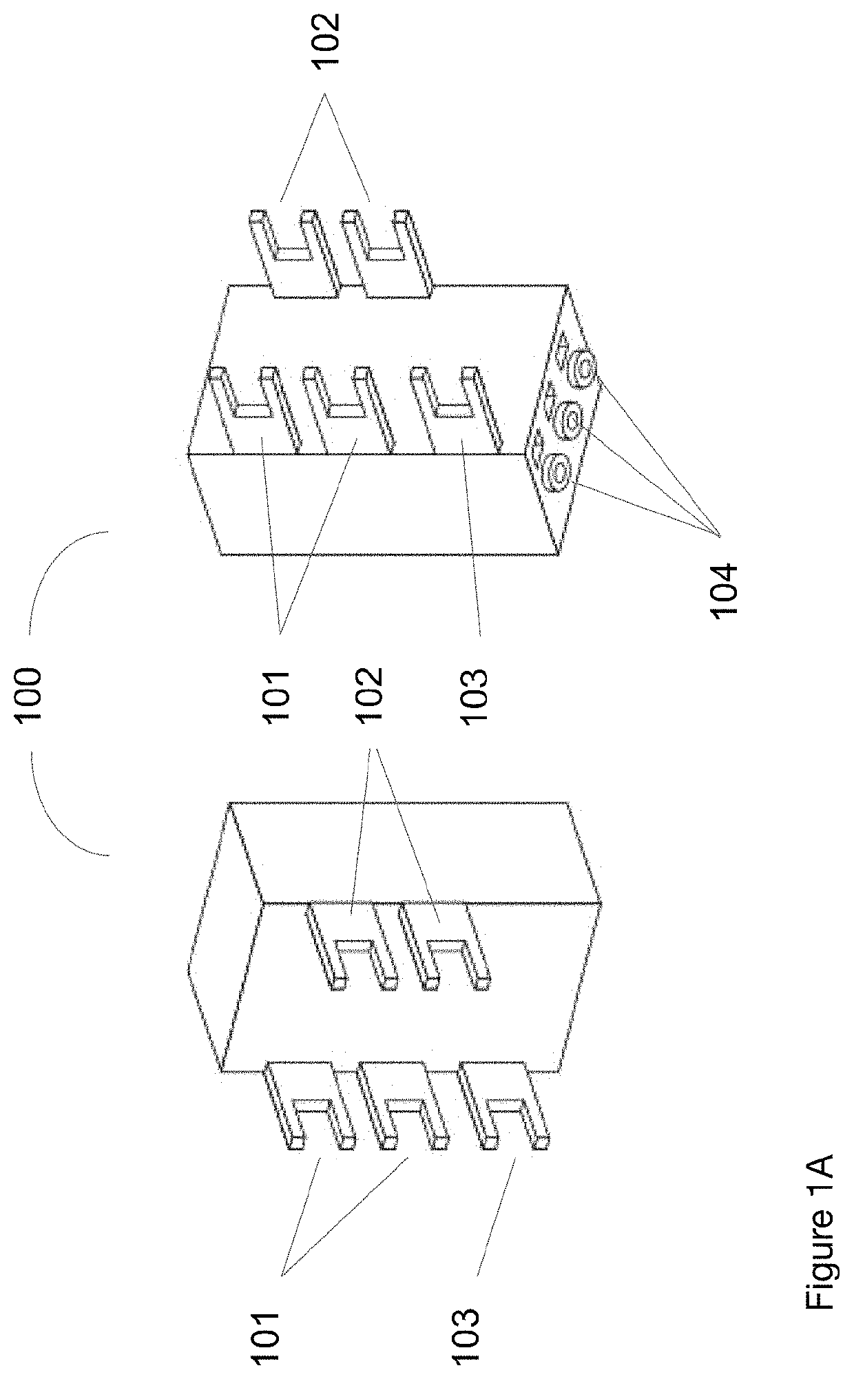
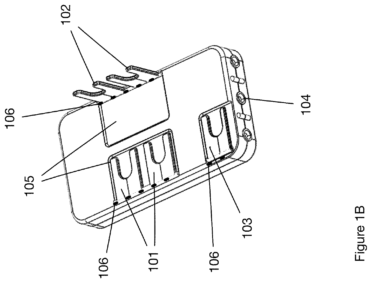
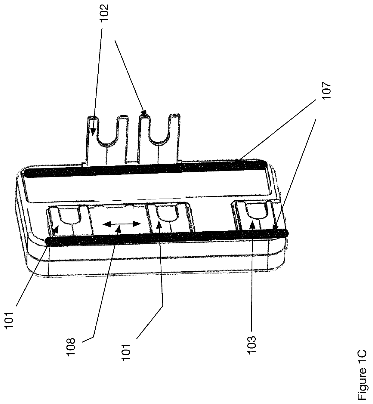
[0043]FIG. 1C shows the multifunctional system integrator of FIG. 1A wherein at least one of the terminals 101, 102, 103 are mounted within slots 107 that enable movement of the terminals 101-103 in the direction 108. In one embodiment the terminals 101-103 are disconnected from the electronics within the multifunctional system integrator 100 when in the lowered position as shown for terminals 101, 103 and connected to the internal electronics when in the raised position as shown for terminals 102. The terminals and the multifunctional system integrator further include a slide and lock mechanism within the slots 107 that enable movement in the direction 108 when in a lowered position as shown for terminals 101, 103 and are locked in place when raised as shown for terminal 102.

[0044]FIG. 2 shows a left side view of a duplex receptacle 200 aligned with the controller module 100. The output terminals for the hot supply line 102 on module 100 are aligned with the input terminals 202 for...

second embodiment

[0050]FIG. 7 shows an assembly 700 including a second embodiment assembly controller module 701 attached to a duplex receptacle 200 and aligned with a standard electrical box 401 and a removable user interface faceplate 702. Module 701 includes a user interface control circuit that attaches to faceplate 702 using flexible ribbon cable 705. The figure shows user interface controls for the Reset 703 and Test 704 functions that are associated with a GFCI capability.

[0051]FIG. 8 shows a typical room 801 in a house that include outlets 802, switches 803 and other electrical devices such as hard wired lighting 804. Each of the devices 802 would include electrical boxes that in the present invention include the electronics described in FIGS. 1-7 and the following Figures. FIG. 9 shows a typical building that includes a plurality of rooms. The floor plan includes a main building 901 and a nearby building 902. Typically, these would represent a house 901 and a garage 902. However, the invent...


PUM


Abstract

An element of a building automation system is described that comprises a multifunctional system integrator contained in a standard receptacle gang box for outlets. The system provides enhanced safety and security, power metering, power control, and home diagnostics. The module can include an AC to DC power supply, a bidirectional solid state dimmer switch, a microprocessor, a communications subsystem and sensors that are controlled by the internal microprocessor. The module includes a user interface for programming and control. The apparatus replaces existing outlet receptacles with a familiar flush but elegantly updated and seamlessly integrated faceplate.

Description

CROSS-REFERENCE TO RELATED APPLICATIONS[0001]Not applicable.STATEMENT REGARDING FEDERALLY SPONSORED RESEARCH OR DEVELOPMENT[0002]Not Applicable.BACKGROUND OF THE INVENTIONTechnical Field[0003]The invention generally relates to the fields of power management and building automation.Background of the Invention[0004]The National Electrical Code (NEC), first published in the year 1897 and updated every three years, is the United States standard for safe installation of electrical wiring and equipment. NEC requirements have been added or updated over the years based upon safety considerations. In 1971, Ground-Fault Circuit Interrupters (GFCI) were added. In 1999, Arc-Fault Circuit Interrupters (AFCI) were added. In 2014, tamper-resistant (TR) electrical receptacles were added. In each case as requirements are added or updated they must be met in new or renovated dwellings.[0005]The most common receptacle in the home is rated for 15 amps. NEC code allows a 15 amp receptacle on a 20 amp ci...

Claims


Application Information

Patent Timeline
Patent Type & Authority Patents(United States)
IPC IPC(8): H04L12/28H01R13/717H01R24/78H01R25/00
CPCH01R13/7175H01R25/006H04L12/2803H01R24/78H04L2012/285H01R4/34H02J3/00H02J7/34H02J1/00
Inventor TELEFUS, MARKLARSON, BRADLEYRODRIGUEZ, HARRYGERBER, STEPHEN C.CASEY, THARCASEY, CHRIS
Owner INTELESOL LLC
Why Eureka
Try Eureka