
Spacecraft collision-avoidance propulsion system and method

a propulsion system and spacecraft technology, applied in the field of spacecraft collision avoidance propulsion system and method, can solve the problems of existing debris continuing to represent a danger, satellites out of operation, collision fragments that represent an ongoing threat,

Active Publication Date: 2020-10-27
DREXLER JEROME
View PDF14 Cites 1 Cited by
  • Summary
  • Abstract
  • Description
  • Claims
  • Application Information

AI Technical Summary

Problems solved by technology

One prime example of the danger is the 2009 accidental collision between Cosmos 2251 and Iridium 33, which not only knocked the satellites out of operation but also generated collision fragments that represent an ongoing threat to other spacecraft.
Even so, existing debris continues to represent a danger and the introduction of small satellites (<500 kg mass) including CubeSats will represent a challenge to collision avoidance.
This adds to the satellite's overall mass.
The energy expense of generating muons artificially in particle accelerators combined with their short lifetimes has limited its viability as an Earth-based fusion source, since it falls short of break-even potential.
Although some fusion events can be observed with as little as 10 KeV acceleration, fusion cross-sections are sufficiently low that accelerator-based particle-target fusion are inefficient and fall short of break-even potential.

Method used


Image

  • Spacecraft collision-avoidance propulsion system and method
  • Spacecraft collision-avoidance propulsion system and method
  • Spacecraft collision-avoidance propulsion system and method

Examples


Embodiment Construction

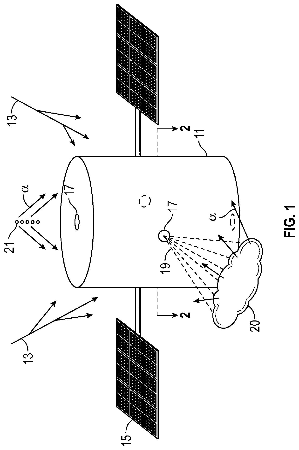
lass="d_n">[0019]With reference to FIG. 1, one technique is to project the fusion target material outward from a spacecraft 11. In the example shown, the spacecraft 11 is a satellite, but other types of spacecraft can also have need of collision-avoidance propulsion systems. The satellite 11 can be powered by solar panels 15 (or alternatively, some internal power source) for its primary mission needs, but also for space object detection and external communication for ground-based collision warning. When an indication of an impending potential collision is detected or received, the collision-avoidance propulsion system will be activated to supply a desired change in trajectory to the satellite or other spacecraft 11.

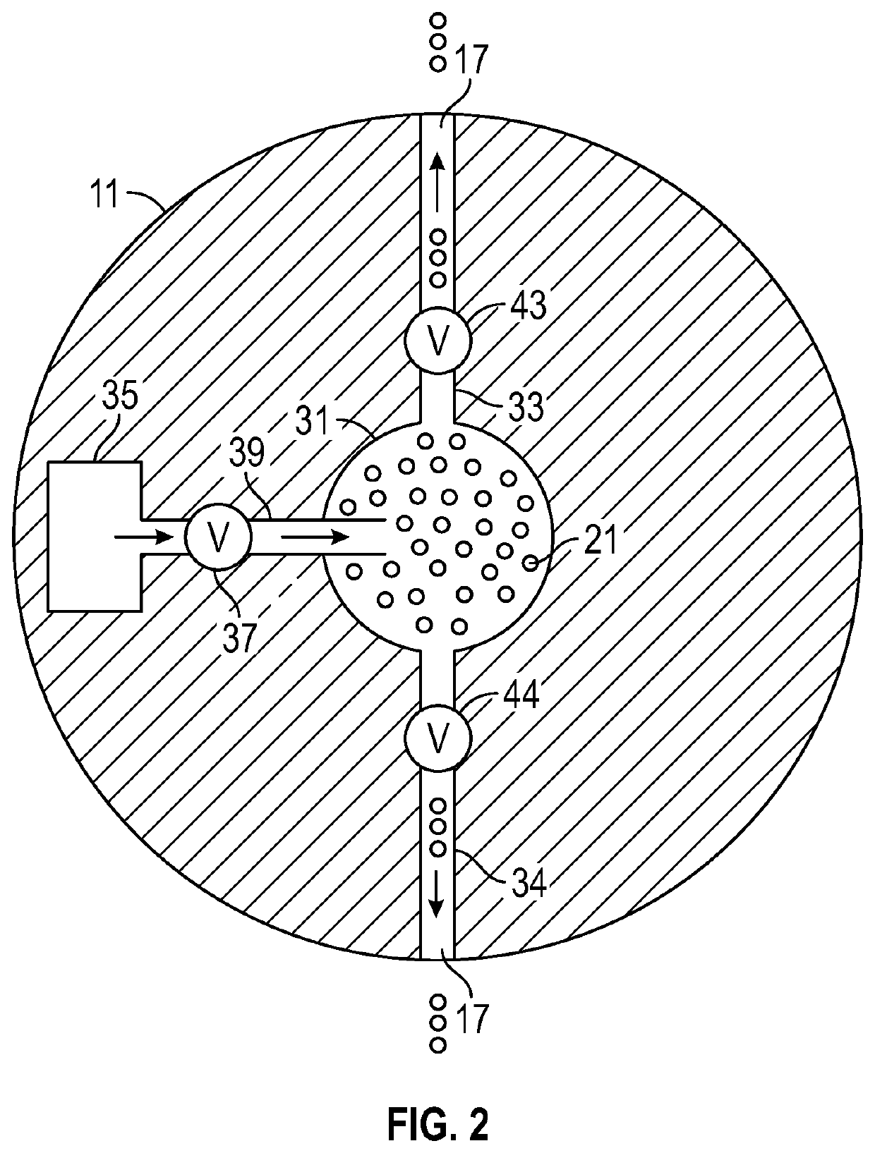
[0020]For this purpose, a supply of deuterium-containing micro-fusion “fuel” material is provided, which can be solid Li6D in powder form, D-D or D-T inertial-confinement-fusion-type pellets, D2O ice crystals. When thrust is needed, one shoots “fuel” pellets 21 as a serie...


PUM


Abstract

A collision-avoidance propulsion system and method for orbiting satellites and other spacecraft takes advantage of ambient cosmic rays in space to catalyze micro-fusion events via particle-target fusion and muon-catalyzed fusion processes, using the reaction products to produce thrust upon orbiting satellites and other spacecraft. A supply of deuterium-containing particle fuel material is propelled in a specified direction of the spacecraft in response to indication of a potential collision with another space object (e.g. orbiting debris). In one embodiment, this may be performed by propellant gas expelling the fuel material through conduits to specified ports on the exterior of the spacecraft. The propelled material interacts with the ambient cosmic rays and muon generated from those cosmic rays to induce micro-fusion. A portion of the energetic reaction products (e.g. alpha particles) are received upon the spacecraft to alter its trajectory in a manner that avoids the potential collision.

Description

TECHNICAL FIELD[0001]The present invention relates to providing thrust to orbiting satellites and other spacecraft, for collision avoidance and other trajectory or orbital adjustments, and further relates to inducement of controlled muon-catalyzed nuclear micro-fusion, as well as micro-fusion obtained from fuel bombardment with high-energy particles (particle-target fusion).BACKGROUND ART[0002]Many thousands of known pieces of debris are present in low Earth orbit (LEO). The United States Strategic Command tracks nearly 20000 artificial objects in orbit that are large enough to be detected. These not only include nearly 2000 operational satellites, but many more defunct payloads, intact rocket bodies (mainly second-stage boosters), and explosion / collision debris fragments. Over 500,000 undetected objects larger than about 1 cm are estimated to be in orbit. Because of the potential hazards to operational satellites, those satellites are equipped with Whipple shielding to dissipate ki...

Claims


Application Information

Patent Timeline
Patent Type & Authority Patents(United States)
IPC IPC(8): B64G1/56B64G1/26B64G1/40B64G1/52G21H7/00G21B3/00
CPCB64G1/26B64G1/408B64G1/52G21B3/004G21H7/00B64G1/56B64G1/242B64G1/105G21B1/19Y02E30/10B64G1/1064
Inventor DREXLER, JEROME
Owner DREXLER JEROME
Learn More