
Air cart fan control

a technology for air carts and fans, applied in the field of systems, can solve problems such as air waste by users and blockage in the system

Active Publication Date: 2020-11-03
CNH IND CANADA
View PDF14 Cites 12 Cited by
  • Summary
  • Abstract
  • Description
  • Claims
  • Application Information

AI Technical Summary

Benefits of technology

The present invention relates to a system for conveying particulate material, such as seed or fertilizer, in an air flow to an agricultural field. The invention addresses the problem of blockages in the system caused by the pressure gradient or differential in the product distribution line. The invention uses pressure sensors to monitor the air flow and adjust it to maintain an optimum operating velocity above the critical air speed but below a maximum air speed that causes inefficient operation. The system can adjust the air source to control the air flow and can also manipulate the hose routing to respond more quickly to changes in the product rate. The invention also monitors the product flow status in real-time to prevent blockages and can adjust the fan based on the product rate to save power and achieve safer conveying conditions. The system can also use changes in cross-sectional dimensions of the pneumatic conveying pipe / hose to determine if deviations from the current state of the system will increase the risk of plugging the system. The invention provides a self-learning system that can determine where the pressure minima is for each product and predict well in advance before arrival in the pressure minima region, ensuring safe and efficient conveying.

Problems solved by technology

Below the critical air speed, the particulate material may become susceptible to falling out of the air flow to potentially cause a blockage in the system.
However, with the increasing use of variable product application rates across the tool (varying seed and / or fertilizer rates according to a prescription map) a user may be wasting air.

Method used


Image

  • Air cart fan control
  • Air cart fan control
  • Air cart fan control

Examples


Embodiment Construction

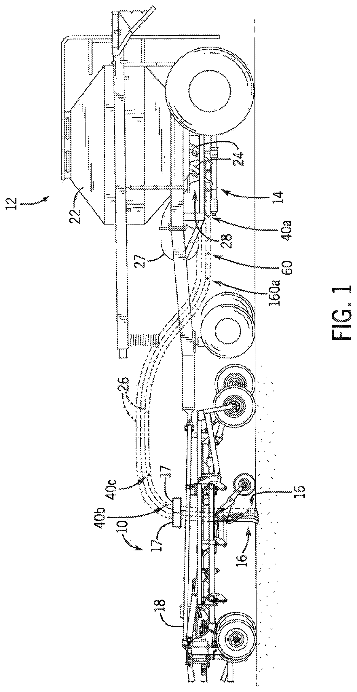
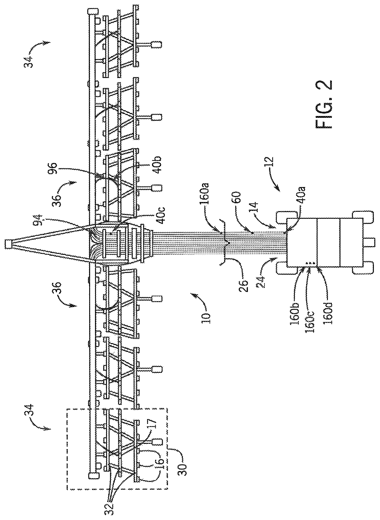
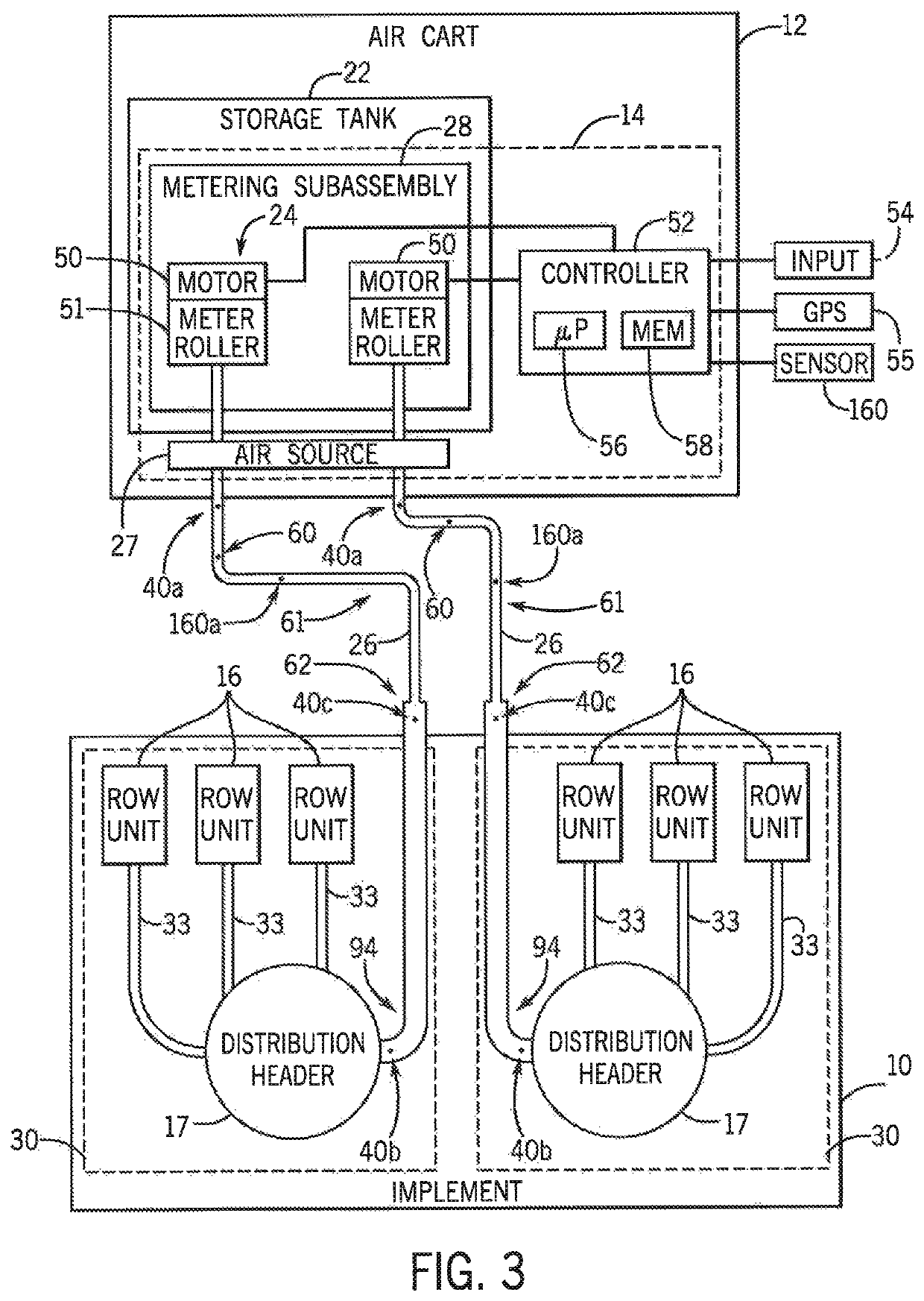
[0024]Referring now to the drawings and specifically to FIG. 1, a side view of an exemplar agricultural implement 10, which may be a seeding implement or tool, coupled to an air cart 12 having a control system 14 is provided in accordance with an aspect of the invention. The implement 10 includes multiple row units 16 and multiple distribution headers 17 supported by a frame 18. Each distribution header 17 is configured to receive agricultural particulate material, such as seed or fertilizer, from the air cart 12, and to route the product to each row unit 16. The row units 16, in turn, may be configured to deposit the agricultural product onto the soil as the implement 10 travels across an agricultural field. As shown, the air cart 12 can be coupled to the implement 10 via the frame 18. The air cart 12 may include one or more product storage tanks 22 configured to store one or more agricultural products (particulate material). Each product storage tank 22 is coupled to a correspondi...


PUM


Abstract

A pressure gradient or differential in a product distribution line for conveying granular particulate material, including at least one of seed or fertilizer, in an air flow to an agricultural field consistently decreases as air speed and velocity in the product distribution line decreases until a critical air speed is reached. Below the critical air speed, the particulate material may become susceptible to falling out of the air flow to potentially cause a blockage in the system. Accordingly, pressure sensors arranged in the product distribution line can be used to generate an air flow at an optimum velocity above the critical air speed yet below a maximum air speed associated with inefficient operation. The air flow can be adjusted to maintain the optimum velocity despite changes in at least one of a type of particulate material or a rate at which the particulate material is metered.

Description

FIELD OF THE INVENTION[0001]The present invention relates generally to systems for distributing particulate material to agricultural fields, and more particularly, to such systems having pressure sensors in product distribution lines for conveying the particulate material in which pressure gradients calculated from the pressure sensors are used to control an air source to maintain an air flow at a velocity below a maximum velocity producible by the air source and above a minimum velocity causing a minimum pressure gradient.BACKGROUND OF THE INVENTION[0002]Generally, a tractor or work vehicle tows seeding or fertilizing implements via a hitch assembly that connects to a rigid frame of a planter, seeder or fertilizer applicator. These crop production systems typically include one or more delivery lines that carry particulate material, such as seed or fertilizer. In certain systems, ground engaging tools are used to break the soil to deposit the particulate material carried by these de...

Claims


Application Information

Patent Timeline
Patent Type & Authority Patents(United States)
IPC IPC(8): A01C7/08A01C7/10A01C21/00A01C7/20
CPCA01C21/005A01C7/105A01C7/205A01C7/084A01C15/04A01C7/081A01C7/102Y02P60/21
Inventor GERVAIS, JOELPAULSON, IAN
Owner CNH IND CANADA
Learn More