
Electric control mechanism, and an aircraft

a control mechanism and electric technology, applied in the direction of emergency springs, tumbler/rocker switches, transportation and packaging, etc., can solve the problems of troublesome erratic and/or undeired control orders, and achieve the effect of reliable blade pitch control and quick stop of pitch variation

Active Publication Date: 2020-11-17
EUROCOPTER
View PDF13 Cites 2 Cited by
  • Summary
  • Abstract
  • Description
  • Claims
  • Application Information

AI Technical Summary

Benefits of technology

The control mechanism described in the patent allows for precise stopping of a pilot's control signal. This is accomplished by detecting the movement of a switch, even before the button has returned to its neutral position. The control mechanism also allows for independent and priority control of positioning the blades in a way that generates no thrust.

Problems solved by technology

However, an erratic and / or undesired control order can turn out to be troublesome on board an aircraft, e.g. while flying close to an obstacle.
Nevertheless, when the pilot rocks the button in the first direction, the button returning towards a neutral position might be wrongly considered as a control signal to reduce the collective pitch.

Method used


Image

  • Electric control mechanism, and an aircraft
  • Electric control mechanism, and an aircraft
  • Electric control mechanism, and an aircraft

Examples


Embodiment Construction

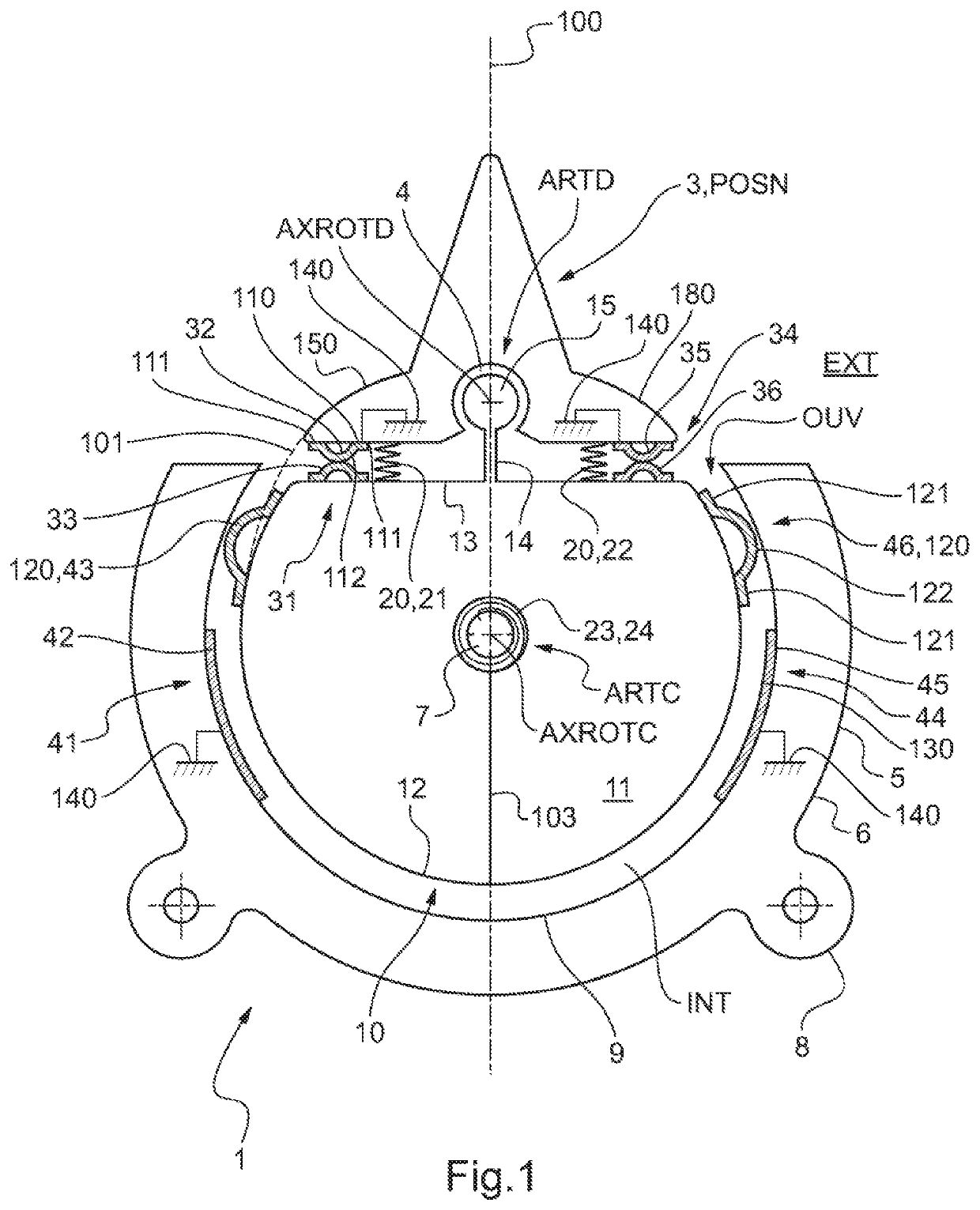
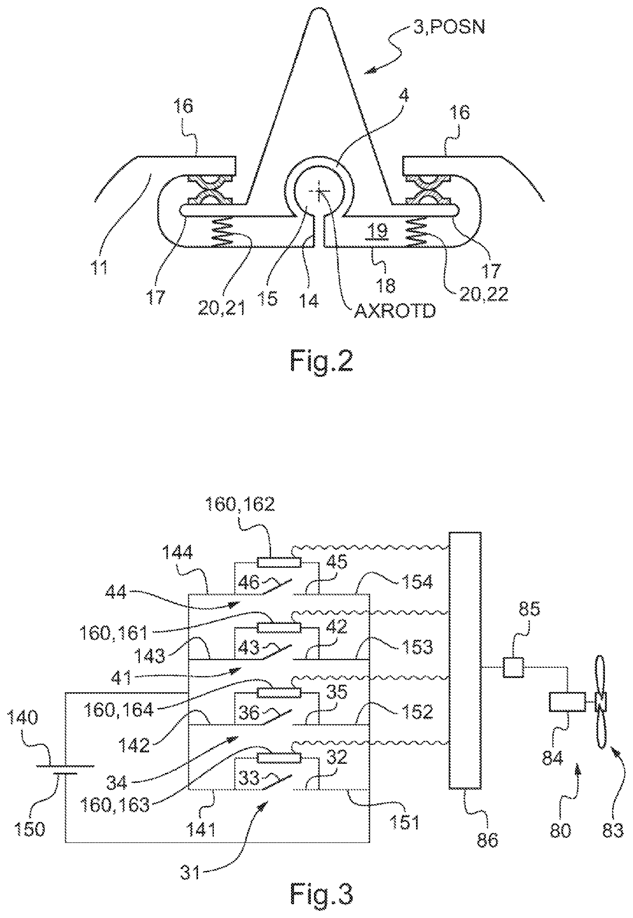
[0077]FIG. 1 shows a control mechanism 1 of the type of the invention.

[0078]The control mechanism 1 has a support 5. The support 5 includes an outer cage 6. The outer cage 6 separates an internal space INT present inside the support 5 from an external medium EXT situated outside the support 5. Nevertheless, the outer cage 6 presents an opening OUV putting the internal space INT into communication with the external medium EXT.

[0079]The outer cage may have an inner support face 9 facing the internal space INT. This inner support face 9 may be in the form of a truncated cylinder on a circular base or it may be in the form of a spherical cap, for example.

[0080]The outer cage 6 may include fastener means 8 enabling the control mechanism to be fastened to a control member, e.g. a control stick. In the example shown, the fastener means comprise lugs 8 for screw-fastening to a member.

[0081]Furthermore, the control mechanism 1 has a central body 10. The central body 10 is arranged at least i...


PUM


Abstract

An electrical control mechanism having a support. A central body that is movable in rotation about a central axis of rotation (AXROTC) carries a button that is movable in rotation relative to the central body about an offset axis of rotation (AXROTD) parallel to the central axis of rotation (AXROTC). First return means are interposed between the central body and the button, with second return means being interposed between the central body and the support. Two primary electric switches are interposed between the button and the central body on either side of a plane containing the central axis of rotation (AXROTC) and the offset axis of rotation (AXROTD). Two secondary electric switches are interposed between the support and the central body on either side of the plane.

Description

CROSS-REFERENCE TO RELATED APPLICATIONS[0001]This application claims priority to French patent application No. FR 1771383 filed on Dec. 19, 2017, the disclosure of which is incorporated in its entirety by reference herein.BACKGROUND OF THE INVENTION(1) Field of the Invention[0002]The present invention relates to an electric control mechanism and to an aircraft.[0003]In particular, the electric control mechanism is adapted to control the collective pitch of the blades of a propeller or of a rotor of an aircraft.2) Description of Related Art[0004]By way of example, a control mechanism may comprise a rocker button in the form of a hat button, i.e. in the form of an upside-down V-shape in section. The control mechanism may be arranged at the top of a stick so that the pilot of an aircraft can manipulate it with a thumb, for example.[0005]It is advantageous to be able to detect accurately the instant at which the pilot voluntarily issues a control order by manipulating the control mechan...

Claims


Application Information

Patent Timeline
Patent Type & Authority Patents(United States)
IPC IPC(8): H01H23/14H01H23/30B64D31/04B64D35/00H01H23/00H01H25/04
CPCH01H23/14H01H25/04H01H23/30B64D31/04H01H23/003B64D35/00H01H2239/03H01H2221/016H01H2225/014H01H2235/028H01H2205/002H01H2205/004
Inventor ABDELLI, KAMELSELLIER, OLIVIER
Owner EUROCOPTER
Learn More