Mattress construction with self inflated air spring

a mattress and air spring technology, applied in the field of mattress construction with self-inflating air springs, can solve the problems of increasing the cost, complicated coil spring mattress construction, and eventually deformation of the spring, and achieve the effect of simple and inexpensive construction, maintaining comfort and durability

Active Publication Date: 2020-11-24
THEOSABRATA YOS SOETANTO
View PDF20 Cites 0 Cited by
  • Summary
  • Abstract
  • Description
  • Claims
  • Application Information

AI Technical Summary

Benefits of technology

[0008]It is therefore an object of the invention to provide an air mattress of simple and inexpensive construction while maintaining comfort and durability.
[0009]It is a further object of the invention to provide an air spring design that allows them to be self inflated.
[0012]These and other related objects are achieved by a multi-layer air mattress having three sections. The layer closest to the user is the upper section having one or more layers of comfort material. The middle layer has dozens of air spring retaining apertures arranged in a matrix. The layer farthest from the user is the lower section having one or more layers of support material. An air spring is located in each of the air spring supporting apertures. The air springs have a sealed internal cavity in communication with an invertible nipple that can be pressed into the internal cavity to reduce the cavity volume and self inflate the air spring.

Problems solved by technology

Over periods of extended use the springs eventually fatigue and deform.
In addition, the construction of coil spring mattresses is complicated which drives up the cost.
Finally, coil spring mattresses are heavy which make it difficult to move them for cleaning or re-positioning.
Coupling air springs together with transfer tubes is an involved process that increases the complexity and cost of the resulting air mattress.
The addition of a ports and a compressor increases the weight of the mattress system.
Most significantly, the tubes and their various connections provide a large number of points where the pressurized manifold and the coupled air springs can leak resulting in the loss of the entire mattress.

Method used


Image

  • Mattress construction with self inflated air spring
  • Mattress construction with self inflated air spring
  • Mattress construction with self inflated air spring

Examples


Embodiment Construction

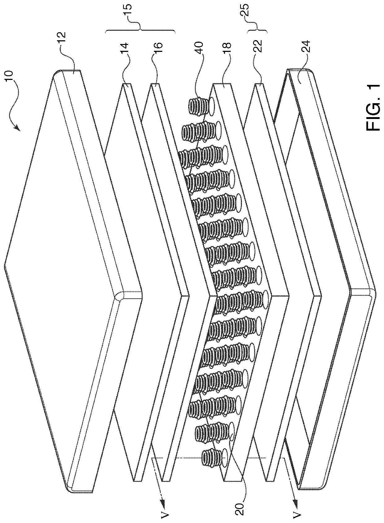
[0025]Referring now in detail to the drawings, and in particular FIG. 1, there is shown an exploded view of an air mattress 10 according to the invention. Air mattress 10 has multiple layers, which can be summarized as a middle layer 18 containing air springs 40 sandwiched between an upper section 15 and a lower section 25. The upper section 15, middle layer 18 and lower section 25 are contained within an outer cover, depicted as top cover 12 and bottom cover 24.

[0026]Upper section 15 includes one or more layers of comfort material. As will be understood by those familiar with mattress construction, the upper section is closest to the user's body and provides a degree of support along with a smooth and pliable texture capable of giving under the various pressure points of the user's body. Comfort material means bedding layers that are primarily pliable and secondarily supportive. In the invention, this is achieved by providing a medium density foam layer 14 set atop a low density fo...


PUM


Abstract

A multi-layer air mattress having an upper section with one or more layers of comfort material and a lower section having one or more layers of support material. A middle layer is arranged between the upper and lower sections and includes apertures for retaining air springs. The air spring has two cups that are sealed to a form plate to create a welded joint that encapsulates a sealed internal cavity. An invertible nipple is pressed into the internal cavity to reduce the cavity volume and self inflate the air spring.

Description

BACKGROUND OF THE INVENTION1. Field of the Invention[0001]The invention relates to a multi-layer mattress construction with self inflated air spring.2. The Prior Art[0002]Mattresses typically found in permanent locations in bedrooms and hotels employ coil springs disposed below one or more layers of comfort material. Over periods of extended use the springs eventually fatigue and deform. In addition, the construction of coil spring mattresses is complicated which drives up the cost. Finally, coil spring mattresses are heavy which make it difficult to move them for cleaning or re-positioning.[0003]To address some of these drawbacks, companies have employed newer comfort materials to provide foam mattresses or air mattresses. For example, U.S. Pat. No. 5,836,027 has a foam mattress with a matrix arrangement of interior cavities. An air spring is located within each of the cavities. Transfer tubes are connected between selected air springs to distribute air between the air springs in r...

Claims


Application Information

Patent Timeline
Patent Type & Authority Patents(United States)
IPC IPC(8): A47C27/18A47C27/14A47C27/05A47C27/08A47C27/06A47C27/20A47C27/15
CPCA47C27/084A47C27/148A47C27/061A47C27/15A47C27/20A47C27/082A47C27/18A47C27/056
Inventor THEOSABRATA, YOS SOETANTO
Owner THEOSABRATA YOS SOETANTO
Why Eureka
Try Eureka