Method and system for mitigating read disturb impact on persistent memory

a technology of persistent memory and read disturb, applied in the field of data storage, can solve the problems of data loss, data modification and/or data loss, data loss, etc., and achieve the effect of facilitating data placemen

Active Publication Date: 2020-12-08
ALIBABA GRP HLDG LTD
View PDF84 Cites 2 Cited by
  • Summary
  • Abstract
  • Description
  • Claims
  • Application Information

AI Technical Summary

Benefits of technology

[0004]One embodiment facilitates data placement in a storage device. During operation, the system receives chunks of data to be written to a non-volatile memory. The system encodes a first chunk based on a first error-correcting code (ECC) to obtain a first ECC-encoded codeword. The system encodes a first group of ECC-encoded codewords which include the first ECC-encoded codeword, based on an erasure code (EC) to obtain a first EC-encoded group, wherein a respective EC-encoded group includes EC parity bits. The system encodes the EC parity bits of the obtained first EC-encoded group based on a second error-correcting code (ECC) to obtain ECC-encoded EC parity bits. The system writes the first EC-encoded group and the ECC-encoded EC parity bits to the non-volatile memory.

Problems solved by technology

One challenge associated with these frequent read operations is the “read disturb,” in which the coupling effect of the memory array can result in data loss.
The accumulation of this coupling effect can create a high raw bit error rate, which can result in data modification and / or data loss.
Thus, the frequent retrieval / reading out of data from the non-volatile memory may result in a significant level of read disturb.
This can result in an increased read amplification, which in turn can exacerbate the read disturb impact, which in turn can increase the burden of the ECC encoding and decoding.
Furthermore, the encoding and decoding complexity of the strong ECC can result in an increased latency.
These challenges can decrease the efficiency and performance of a storage system.

Method used


Image

  • Method and system for mitigating read disturb impact on persistent memory
  • Method and system for mitigating read disturb impact on persistent memory
  • Method and system for mitigating read disturb impact on persistent memory

Examples


Embodiment Construction

[0026]The following description is presented to enable any person skilled in the art to make and use the embodiments, and is provided in the context of a particular application and its requirements. Various modifications to the disclosed embodiments will be readily apparent to those skilled in the art, and the general principles defined herein may be applied to other embodiments and applications without departing from the spirit and scope of the present disclosure. Thus, the embodiments described herein are not limited to the embodiments shown, but are to be accorded the widest scope consistent with the principles and features disclosed herein.

Overview

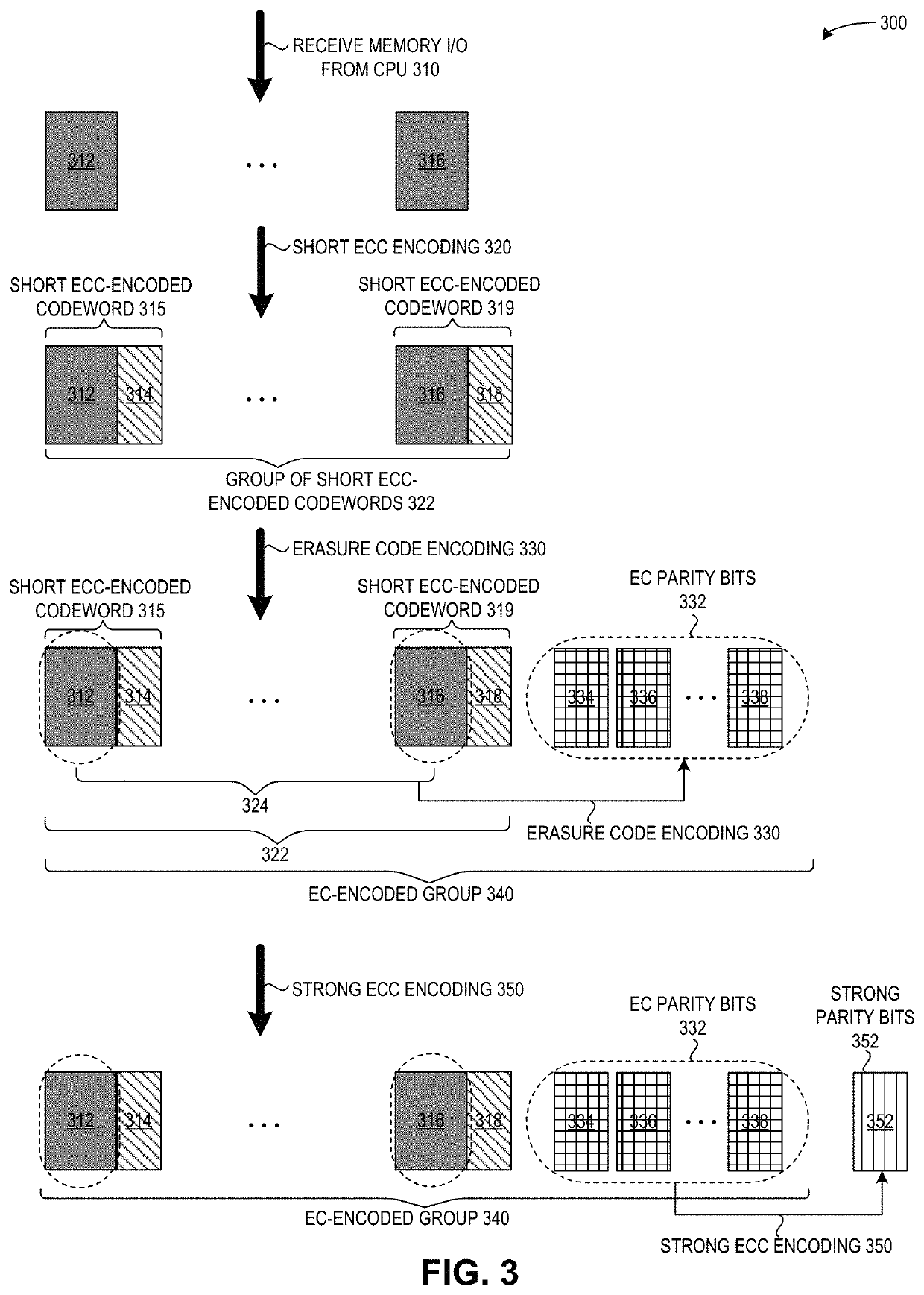
[0027]The embodiments described herein solve the problem of mitigating the read disturb impact on persistent memory by providing three levels of encoding: encoding small chunks using a short (e.g., a weak or a medium) error correcting code (ECC); encoding groups of short ECC-encoded chunks using an erasure code (EC); and encoding the E...


PUM


Abstract

One embodiment facilitates data placement in a storage device. During operation, the system receives chunks of data to be written to a non-volatile memory. The system encodes a first chunk based on a first error-correcting code (ECC) to obtain a first ECC-encoded codeword. The system encodes a first group of ECC-encoded codewords which include the first ECC-encoded codeword, based on an erasure code (EC) to obtain a first EC-encoded group, wherein a respective EC-encoded group includes EC parity bits. The system encodes the EC parity bits of the obtained first EC-encoded group based on a second error-correcting code (ECC) to obtain ECC-encoded EC parity bits. The system writes the first EC-encoded group and the ECC-encoded EC parity bits to the non-volatile memory.

Description

BACKGROUNDField[0001]This disclosure is generally related to the field of data storage. More specifically, this disclosure is related to a method and system for mitigating read disturb impact on persistent memory.Related Art[0002]The proliferation of the Internet and e-commerce continues to create a vast amount of digital content. Various storage systems have been created to access and store such digital content. A storage system or server can include various types of physical media for storage of data, including volatile memory (which needs constant power in order to retain stored data) and non-volatile memory (which can retain stored data despite losing power). Some examples of current non-volatile memory media include magnetoresistive RAM (MRAM), resistive RAM (ReRAM), phase change memory (PCM), nano-RAM (NRAM), and ferroelectric RAM (FRAM). The persistent property of non-volatile memory is increasingly important for applications which require a low-latency but frequent access. T...

Claims


Application Information

Patent Timeline
Patent Type & Authority Patents(United States)
IPC IPC(8): G06F11/10H03M13/15H03M13/29G11C7/02G11C29/52
CPCH03M13/2906G06F11/1068G11C7/02H03M13/154G11C29/52G06F11/1012G11C2029/0411H03M13/2927H03M13/2945H03M13/353
Inventor LI, SHU
Owner ALIBABA GRP HLDG LTD
Why Eureka
Try Eureka