Inner conductor terminal and shield terminal

a shield terminal and inner conductor technology, applied in the direction of coupling contact members, fixed connections, coupling device connections, etc., can solve the problems of inability to maintain predetermined impedance, change in tubular shape between the inner conductor terminal and the outer conductor terminal, and inability to bend the tubular shape, so as to achieve good high-frequency signal and prevent the effect of impedance mismatch between the first and second terminal portions

Active Publication Date: 2020-12-08
SUMITOMO WIRING SYST LTD
View PDF47 Cites 6 Cited by
  • Summary
  • Abstract
  • Description
  • Claims
  • Application Information

AI Technical Summary

Benefits of technology

[0007]The bent portion is provided between the first and second terminal portions and covers the openings of the respective open ends of the first and second terminal portions. Additionally, side portions cover the clearance between the bent portion, the first terminal portion and the second terminal portion from the both sides. Thus, a space between the first and second terminal portions is surrounded by the bent portion and the side portions. In this way, an impedance mismatch between the first and second terminal portions can be prevented. As a result, impedance matching is possible and the transmission of a good high-frequency signal can be achieved.

Problems solved by technology

However, the above-described inner conductor terminal has a bend at an intermediate position and it is difficult to bend the tubular shape.
If a clearance is formed in the inner conductor terminal due to the tubular shape interrupted at the bent part, a distance between the inner conductor terminal and the outer conductor terminal changes and a predetermined impedance cannot be maintained.
As a result, an impedance mismatch may be caused at the bend of the inner conductor terminal and a good transmission characteristic of a high-frequency signal may be impaired.
For example, an opening part of the accommodating portion could be formed and reduced in diameter, and the thickness of the dielectric would change, thereby making it difficult to precisely match impedances.

Method used


Image

  • Inner conductor terminal and shield terminal
  • Inner conductor terminal and shield terminal
  • Inner conductor terminal and shield terminal

Examples


Embodiment Construction

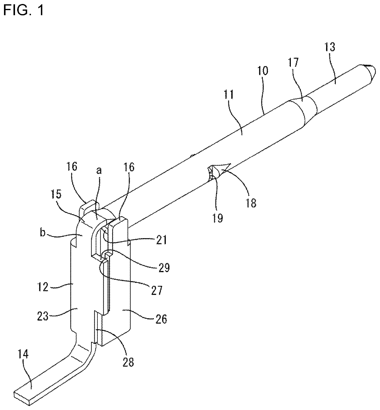
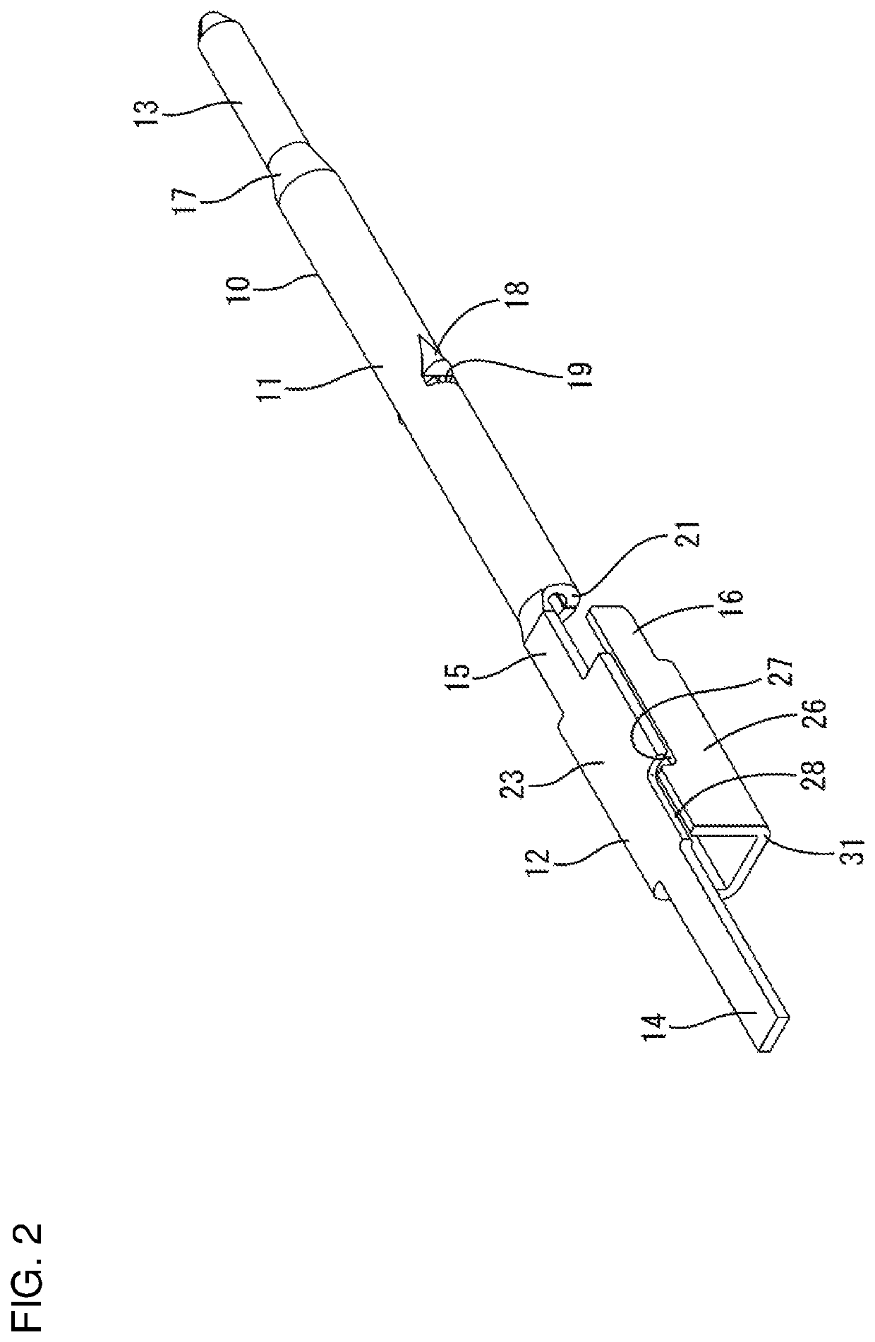
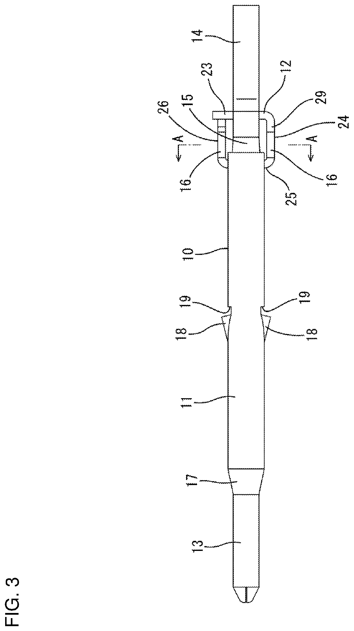
[0020]One embodiment of the invention is described with reference to FIGS. 1 to 9. An inner conductor terminal 10 of this embodiment is configured as one component of a shield terminal 100. The shield terminal 100 includes a dielectric 40 and an outer conductor terminal 60 besides the inner conductor terminal 10. The shield terminal 100 is accommodated in a connector housing 80.

[0021](Connector Housing 80)

[0022]The connector housing 80 is made of synthetic resin and is disposed on a surface (upper surface) of a circuit board 90, as shown in FIG. 9. The connector housing 80 includes a mounting portion 81 substantially along a vertical direction and a receptacle 82 projecting forward (right in FIG. 9) from the outer periphery of the mounting portion 81. A through hole 83 penetrates the mounting portion 81 in a front-rear direction.

[0023](Outer Conductor Terminal 60)

[0024]The outer conductor terminal 60 is formed integrally, such as by bending a conductive metal plate. The outer conduc...


PUM


Abstract

An inner conductor terminal (10) is made of a metal plate and includes tubular first terminal portion (11) and second terminal portion (12) each having an opening end. A bent portion (15) links the first and second terminal portions (11, 12) and covers the respective opening ends of the first and second terminal portions (11, 12) by facing the openings. A tab (13) projects from an end of the first terminal portion (11) opposite to the opening end, and a lead (14) projects from an end part of the second terminal portion (12) opposite from the opening end. The inner conductor terminal (10) includes two side panels (16) projecting from the second terminal portion (12) to be located at both sides of the bent portion (15) and covering a clearance between the bent portion (15), the first terminal portion (11) and the second terminal portion (12) from both sides.

Description

BACKGROUNDField of the Invention[0001]The invention relates to an inner conductor terminal and a shield terminal.Related Art[0002]Japanese Unexamined Patent Publication No. 2012-22885 discloses a shield terminal with an inner conductor terminal, an outer conductor terminal covering the outer periphery of the inner conductor terminal and a dielectric provided between the inner conductor terminal and the outer conductor terminal. The shield terminal is accommodated in a connector housing disposed on a surface of a circuit board.[0003]The inner conductor terminal includes a pin-like connecting portion, a rectangular press-in portion behind the pin-like connecting portion, and a terminal body behind the rectangular press-in portion. The inner conductor terminal is inserted into a terminal accommodating portion of the dielectric from behind. The pin-like connecting portion is cylindrical, projects forward of the dielectric and is connected to a mating terminal. The rectangular press-in p...

Claims


Application Information

Patent Timeline
Patent Type & Authority Patents(United States)
IPC IPC(8): H01R4/10H01R13/6473H01R12/57H01R13/405H01R13/6592H01R13/04
CPCH01R13/04H01R13/6592H01R12/57H01R13/6473H01R13/405H01R13/02H01R13/6474H01R24/44H01R24/50H01R12/724H01R2103/00
Inventor HASHIMOTO, NORIHITOKANEMURA, KEISUKEKUBOTA, MOTOKIKANG, LIPINGMITSUI, SHOHEIYAMANAKA, WATARUKASUGA, MASANOBUHIRANO, AI
Owner SUMITOMO WIRING SYST LTD
Why Eureka
Try Eureka