Heat exchangers, boilers, and systems incorporating the same

Active Publication Date: 2014-09-11
MOSI CHU IRREVOCABLE TRUST
View PDF5 Cites 1 Cited by
  • Summary
  • Abstract
  • Description
  • Claims
  • Application Information

AI Technical Summary

Benefits of technology

The present patent provides improved heat exchange efficiency in boilers and systems by minimizing the dominant resistance against heat exchange. This is achieved by minimizing the impedance mismatch between the source and receiver media, which allows the source medium to deliver a greater percentage of its energy to heat the receiver medium via the least resistance path. The patent describes specific configurations of the primary and secondary exchangers that are designed to minimize the dominant resistance. The boilers and systems can also be dynamically adjusted using microprocessor-based intelligence and other control or feedback systems to maximize efficiency.

Problems solved by technology

However, resistance in such conventional boilers results in much of the heat energy escaping as waste, severely reducing the efficiency of these boilers.
Unfortunately, confinement of the source medium within the boiler is not easily achieved because the source medium has a tendency to escape and the hotter the source medium, the faster it escapes.
Regardless of how turbulent the source medium becomes, it cannot deliver enough energy for the receiver medium to absorb to sufficiently heat the receiver medium before the source medium escapes through the chimney.
This is because of an impedance mismatch between the source medium and the receiver medium that exists in conventional boilers.
This impedance mismatch in conventional boilers stems from the fact that the energy densities (BTU / ft3) of the source medium (typically a gaseous fume) is several orders of magnitude less than that of the receiver medium (typically liquid water), due to the different thermodynamic parameters, e.g., density (lb / ft3), specific heat (BTU / lb×° F.
Such a severe impedance mismatch between the energy provider, i.e., the source medium, and the energy receiver, i.e., the receiver medium, renders the source medium unable to adequately transfer heat to the receiver medium and, as a result, conventional boilers are inefficient.

Method used


Image

  • Heat exchangers, boilers, and systems incorporating the same
  • Heat exchangers, boilers, and systems incorporating the same
  • Heat exchangers, boilers, and systems incorporating the same

Examples


Embodiment Construction

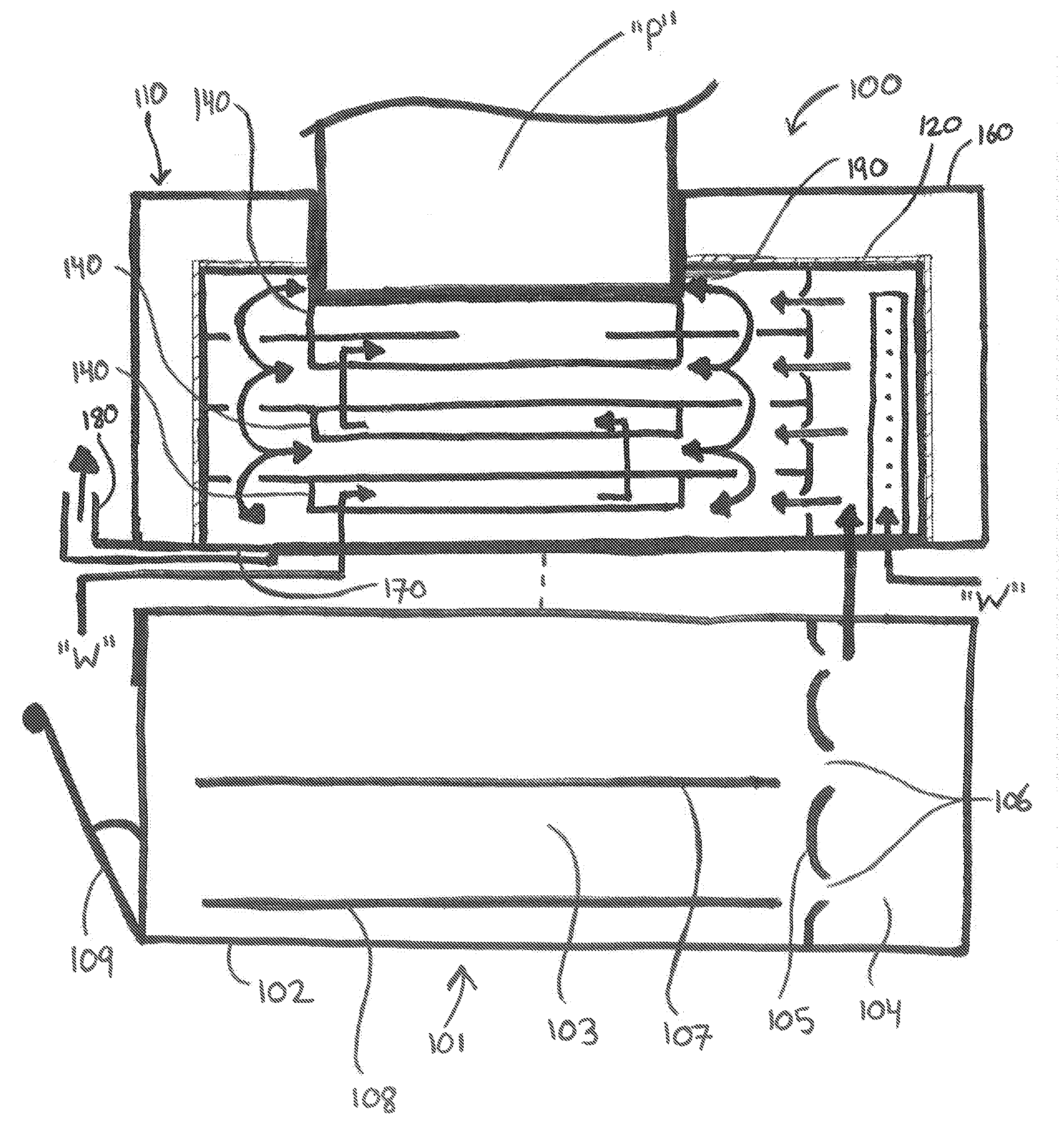
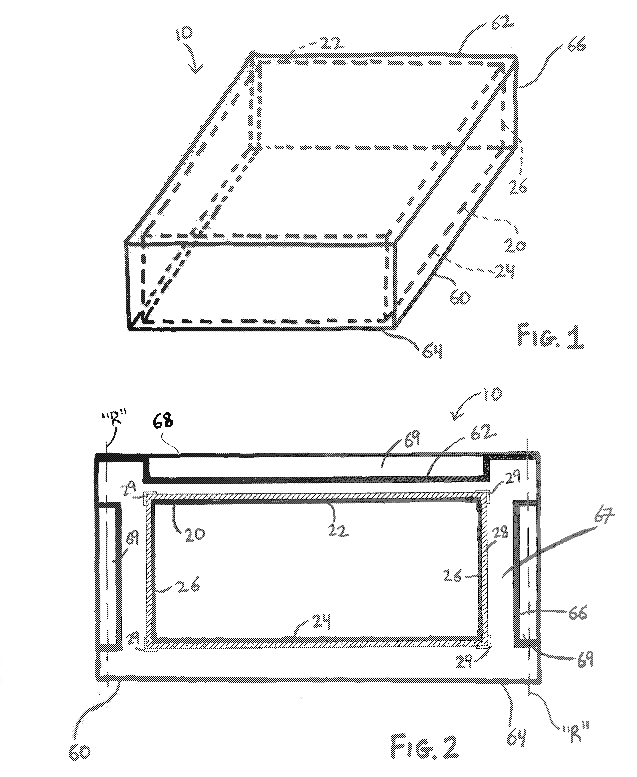
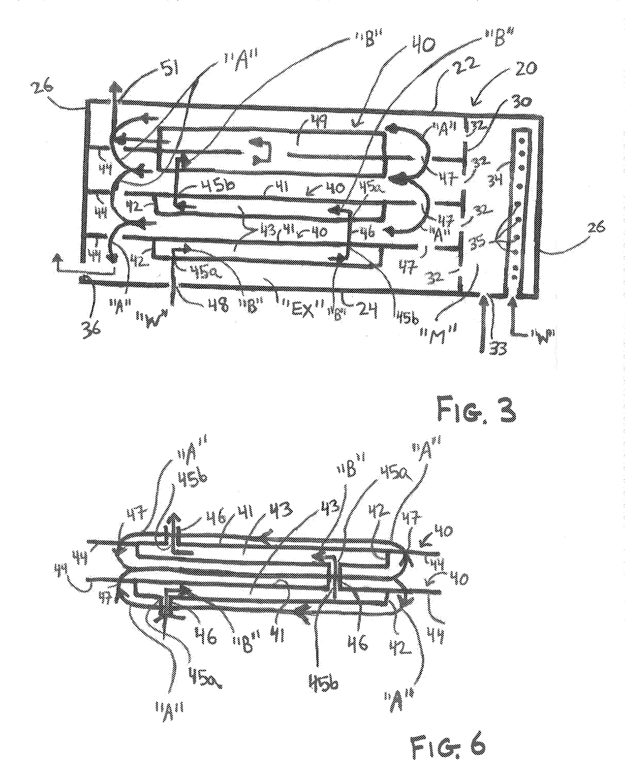
[0046]Various embodiments of the present disclosure will now be described in detail with reference to the drawings, wherein like reference numerals identify similar or identical elements. In the following description, well known functions or constructions are not described in detail to avoid obscuring the present disclosure. To the extent consistent, any of the aspects and / or features of any of the embodiments detailed herein may be used in conjunction with any of the aspects and / or features of any of the other embodiments detailed herein.

[0047]The present disclosure provides heat exchangers, boilers, and systems incorporating the same wherein the boilers generally include a fume generator, and a primary heat exchanger for heating a receiver medium using the source medium from an approximately room temperature liquid to a hot liquid and / or vapor. In some embodiments, depending on a particular purpose, a secondary heat exchanger is provided for further heating the receiver medium to ...


PUM


Abstract

A heat exchanger includes an enclosure having a separator disposed therein that divides the heat exchanger into a mixing area and a heat exchange area. The mixing area is configured to receive a hot fume and droplets of a liquid for mixing with each other to form a fume-droplet vapor mixture. The mixture is configured to flow through orifices of the separator into the heat exchange area. A plurality of magazines is disposed within the heat exchange area of the first enclosure. Each magazine defines a cavity. The cavities are disposed in communication with one another. A lower-most magazine is configured to receive a receiver medium that is pumped through the cavity of each successive magazine to an upper-most magazine. The mixture is configured to circulate about the magazines to incrementally heat the receiver medium as the receiver medium is pumped through the cavity of each successive magazine.

Description

CROSS-REFERENCE TO RELATED APPLICATIONS[0001]This application claims the benefit of, and priority to, U.S. Provisional Patent Application No. 61 / 774,790, filed on Mar. 8, 2013, the entire contents of which are hereby incorporated herein by reference.BACKGROUND[0002]1. Technical Field[0003]The present disclosure relates to boilers and, more particularly, to efficient boilers configured to heat a receiver medium, e.g., water, from an approximately room temperature liquid to a hot liquid, vapor, and / or superheated vapor (depending on the particular purpose). The present disclosure also relates to systems incorporating such boilers, e.g., stove systems, home heating systems, power generating systems, etc.[0004]2. Background of Related Art[0005]In conventional boilers, a source medium, e.g., a hot gaseous fume, is utilized to heat a receiver medium, e.g., water, via heat exchange through a thermally conductive exchange material disposed therebetween. However, resistance in such conventio...

Claims


Application Information

Patent Timeline
IPC IPC(8): F01K7/16F24H1/10F28D1/047
CPCF01K7/16F28D1/047F24H1/107F01K21/04F22B9/02F22B37/40F22D1/30F24H1/10F24H8/003Y02B30/00F22D1/32F22D1/28
Inventor CHU, MOSI
Owner MOSI CHU IRREVOCABLE TRUST
Why Eureka
Try Eureka