FOG disposal article

a technology of disposal articles and fog, applied in the field of articles, can solve the problems of time-consuming and even dangerous disposal of fog in hot liquid form, affecting the quality of cooking byproducts, and causing additional mess, so as to reduce the risk of contamination, and avoid contamination. , the effect of reducing the risk of contamination

Active Publication Date: 2020-12-22
SANTOS SHAWN ALAN
View PDF30 Cites 1 Cited by
  • Summary
  • Abstract
  • Description
  • Claims
  • Application Information

AI Technical Summary

Benefits of technology

[0013]According to another embodiment, a method for disposing FOG is disclosed. The method may include positioning at least one edge of a container on a first bottom surface of a sink surrounding a first drain of the sink so that a top opening of a top portion of the container is facing upward, and at least some of a body portion of the container lies below the first bottom surface and within the first drain. In some examples, the body portion having a FOG-impermeable membrane. In some examples, the method may also include pouring the FOG through the top opening and into the body portion of the container, the container preventing the FOG from passing down the first drain.
[0021]In some examples, article embodiments may also comprise an interior section of absorbent material, for converting FOG absorbed thereby from a liquid or semi-liquid state to a solid or semi-sold state. In one embodiment, the absorbent material may be at least partly enclosed by the exterior membrane to prevent the FOG from passing through the (potentially oversaturated) absorbent material and into the drain pipes. In some embodiments, the entire lower interior of the membrane body may be filled with absorbent material. Absorbent material may be configured to receive FOG through the top opening. Said absorbent material may also comprise material(s) and designs (as described in more detail below) or other absorbent means for maximizing the amount of FOG capable of being absorbed given the limited body volume (or container size for embodiments comprising containers). The FOG absorbent material in one embodiment may comprise polyurethane, and in one particular embodiment may also resemble a foam sponge comprised of cellulose material (such as wood pulp or other earth-friendly substance). In some embodiments, the entire article and / or the parts thereof may be disposable and / or biodegradable. For embodiments comprising absorbent means, with the FOG converted from a liquid state into an at least semi-solid state, the container may be placed in the trash with less risk that puncturing of the container will result in the FOG contents leaking into the remainder of the refuse.
[0023]In one embodiment, the article may comprise a predetermined size and / or body volume (and amount of absorbent material) for holding an amount of FOG cooking byproduct tailored to a single instance of home cooking. For example, in one particular embodiment the body may have a volume for holding substantially four ounces of FOG and absorbent means configured to receive FOG in a maximum amount within the body volume. A size intended for optimally-efficient one-time use, without requiring additional instances of usage, to efficiently utilize and not waste container material, may allow a user to omit burdensome and time-consuming disposal steps, such as storage, sealing and unsealing a lid multiple times, and placing the container in a refrigerator or freezer.
[0024]In one embodiment, the exterior membrane of the body configured for placement in the hollowed inward portion of the drain is rigid (for among other benefits preventing hot liquid FOG poured thereon from compromising the figure of the membrane) and forms a container that stably rests in the drain while FOG is poured into the container through the top opening, with the container sides not stretching substantially above the level of the kitchen sink bottom surface, thus allowing a cooking instrument from which the FOG is poured to be held at a lower elevated and more advantageous position. In some container embodiments, the exterior membrane comprises a rigid outer shell for receiving, holding, and disposing of FOG, which may be separable from the portion of the article comprising the absorbent means. Thus, in some embodiments the FOG absorbent or adsorbent means may be disposed of without the rest of the article also having to be thrown away. In other container embodiments, the entire article may be designed for convenient disposal along with the FOG absorbent / adsorbent means.
[0025]The shape of the body configured for placement in a drain may also provide greater stability and less awkward handling while pouring FOG. Moreover, in one embodiment, the body may comprise an inside surface that may be continuously downward sloping, to facilitate continued downward flow of FOG due to gravity and filling of the lowest part of the interior of the container first, or to otherwise strategically pass liquid FOG to the section of absorbent material. With the article stably placed in a drain, the FOG may be poured therein with less risk of spilling, until at a maximum the FOG absorbent means has been fully saturated and / or until an adsorbent means has also reached its full capacity. In one embodiment, the article body may comprise a rigid, flat bottom surface for placement of the container on another flat surface, such as a countertop, with less worry of the FOG spilling. In one particular embodiment having downwardly sloping sides (and as described in more detail in the Description of the Drawings section), the flat bottom surface may have a width of substantially 2.6 inches. Some embodiments (and not necessarily limited to removable shell or container embodiments) may also comprise other features for more convenient and / or safer handling of the article, such as a perimeter rim comprising legs or knobs or other means for holding the rest of the perimeter rim elevated sufficiently above the bottom surface of the kitchen drain surface (yet still not substantially above the kitchen drain bottom surface) to facilitate grabbing with fingers and removing the article from the drain once the FOG has been poured therein.

Problems solved by technology

The kitchen is often a busy, hectic place where the stress of having to perform certain tasks within or at prescribed times is compounded by potentially dangerous activities, such as handling hot objects and liquids.
Properly disposing of common cooking byproduct FOG in its hot liquid form can be time-consuming and even dangerous.
For example, handling and disposing of hot liquid FOG often entails the risk of spillage from and / or “jumping” in small quantities out of a cooking instrument, which can result in burns, damage to surrounding kitchen objects, not to mention create an additional mess.
On the other hand, waiting to dispose of FOG can be problematic because the FOG may cool, harden, and congeal to a cooking instrument (such as a frying pan), making cleaning and disposal more difficult.
Due at least partly to the lack of attractive alternatives for properly disposing of FOG, FOG is unfortunately often poured in its liquid form down drains, where it flows into drainage pipes.
Once in drainage pipes, the FOG cools, thickens, congeals, and sticks to the pipes, slowing water drainage, and eventually clogging and blocking flow altogether.
This clogging and blogging causes substantial harm, such as destroying septic tanks, resulting in environmental damage (including soil and / or water contamination) and health hazards, emanating noxious smells, and attracting insects and pests.
Conventional methods of removing FOG buildup in pipes are either unsatisfactory or costly.
For example, the common practice of boiling and pouring hot water down the pipes only temporarily liquefies FOG, but does not prevent it from re-solidifying further down the line, where it may cause the same problems.
Similarly ineffective is the method of pouring detergent down drains along with FOG.
Thus, pipes clogged by FOG must often be replaced, which may require the services of a professional plumber.

Method used


Image

  • FOG disposal article
  • FOG disposal article
  • FOG disposal article

Examples


embodiment 13

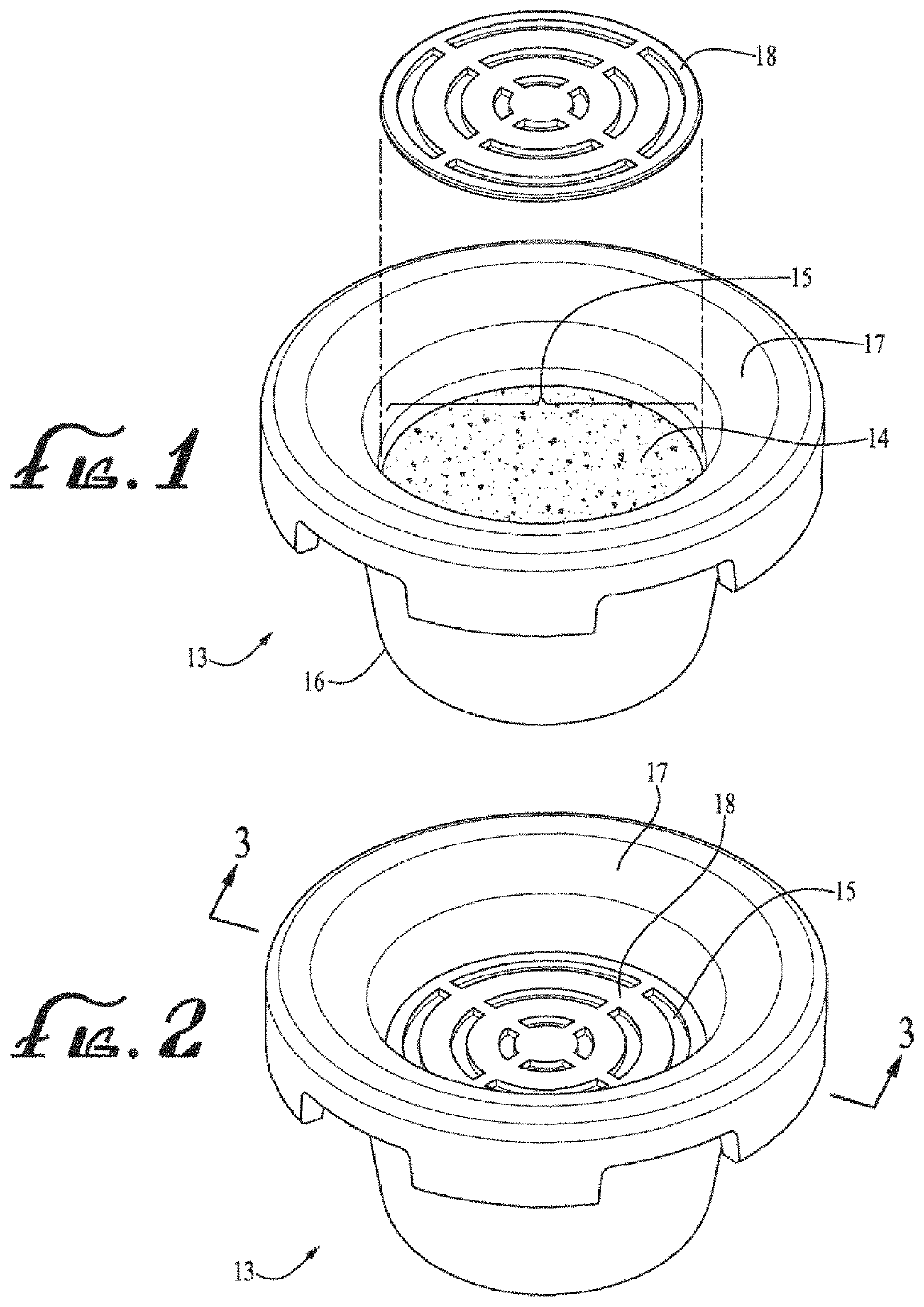
[0058]Turning to the drawings, FIG. 1 illustrates a first article embodiment 13 for disposing of FOG, in accordance with various aspects of this disclosure. The article 13 may comprise absorbent material 14 contained by an outer body perimeter (i.e., exterior membrane forming a body shape) 16, and a top opening 15 above the absorbent material 14 for receiving FOG there-through, the top opening 15 defined by a perimeter rim 17 having a width wider than the body perimeter 16.

[0059]FIG. 2 is a top perspective view of the article of FIG. 1, in accordance with various aspects of this disclosure. The article 13 may also comprise a cover 18 for placement over both the top opening 15 and the absorbent material 14 thereunder. The cover 18, in the embodiment 13 shown, when placed over the top opening 15 defined by the perimeter rim 17, may comprise a design for distributing FOG 19 more evenly over the absorbent material 14.

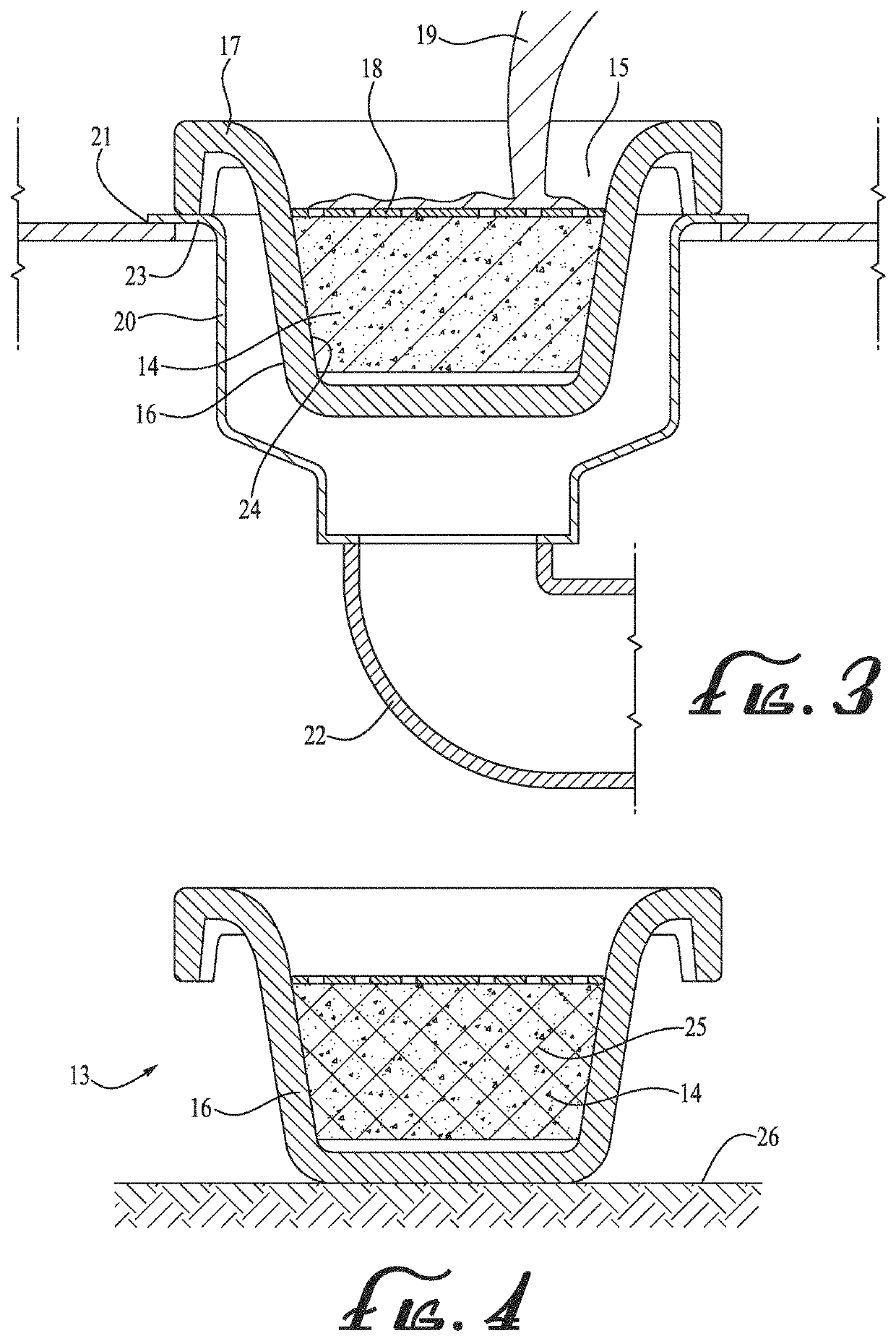
[0060]FIG. 3 is a cutaway cross sectional view of the article of FIG. ...

embodiment 27

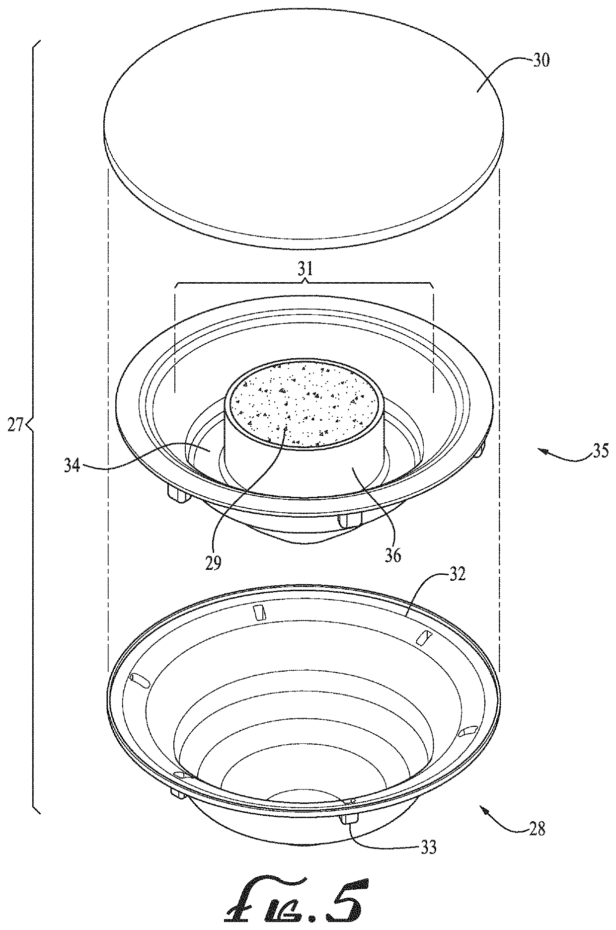
[0064]FIG. 6 is a top perspective view of the unseparated article of FIG. 5, in accordance with various aspects of this disclosure. And FIG. 7 is a cutaway cross sectional view of the article of FIG. 6, placed in a kitchen sink drain, in accordance with various aspects of this disclosure. As shown in FIG. 6, the liner piece 35 may be placed inside the shell / container 28 (and the liner piece 35 may also be removable from the shell / container 28), and as shown in FIG. 7 the filter 30 may be placed over the top opening 31 and the absorbent material 29, and the article 27 may be placed in the drain 20 along a bottom kitchen sink surface 21, with the legs 33 of the perimeter rim 32 resting along the top of the drain 23 so that the shell / container 28 stably rests inside the drain 20. The trough 34 formed by the absorbent side exterior liner / membrane 36 and the downward-middle sloping wall of the liner 35 may capture any excess FOG 19 that was poured into the filter 30 and top opening 31 bu...

embodiment 42

[0066]FIG. 9 is a cutaway cross sectional view of the article of FIG. 8, placed in a kitchen sink drain, in accordance with various aspects of this disclosure. As shown in FIG. 9, the hollowed inward part of the drain 20 may have a middle section 51 and a bottom section 52, and the outer membrane 38 may also have a middle section 53 and a bottom section 54 roughly conforming to the middle section 51 and bottom section 52. As shown in FIG. 9, in some examples, the cross section of the middle section 53 may be greater than the cross section of the bottom section 54, the height of the middle section 53 may be greater than the height of the bottom section 54, and / or the slope of the middle section 53 may be greater than the slope of the bottom section 54. FIG. 10 is a top perspective view of a fourth article embodiment for disposing of FOG, in accordance with various aspects of this disclosure. FIG. 11 is a cutaway cross sectional view of the article of FIG. 10, in accordance with vario...


PUM

PropertyMeasurementUnit
widthaaaaaaaaaa
widthaaaaaaaaaa
heightaaaaaaaaaa

Abstract

An article, a container, and a method for disposing of fat, oil, and / or grease (FOG). The article may include a top portion including a top opening and a perimeter rim, and a body portion connected to and below the top portion having: a continuous FOG-impermeable membrane and upper and lower body portions. The body portion may include a body middle surface dividing upper and lower body portions and may be placed on at least a portion of a surface. The lower body portion may be sized to fit within a drain. The container may include an integrally formed continuous outer shell including a partially hollow interior, a top part having a top opening, and liquid impermeable bottom and upper parts, and a middle part dividing the top and bottom parts and including at least one middle edge for placement on a first surface.

Description

CROSS REFERENCE TO RELATED APPLICATIONS[0001]The application claims benefit of priority to U.S. patent application Ser. No. 15 / 860,212, filed Jan. 2, 2018, which claimed benefit of priority to U.S. patent application Ser. No. 14 / 499,288, filed Sep. 29, 2014, which claimed benefit of priority to U.S. Provisional Patent Application No. 62 / 021,033, filed Jul. 4, 2014, and the entire disclosures of these applications are hereby incorporated by reference in this document.FIELD OF INVENTION[0002]This invention pertains to the field of articles for properly disposing of fat, oil, and / or grease (“FOG”). In particular, the invention relates to articles for preventing FOG from clogging pipes.BACKGROUND OF INVENTION AND DESCRIPTION OF PRIOR ART[0003]The kitchen is often a busy, hectic place where the stress of having to perform certain tasks within or at prescribed times is compounded by potentially dangerous activities, such as handling hot objects and liquids. Properly disposing of common co...

Claims


Application Information

Patent Timeline
Patent Type & Authority Patents(United States)
IPC IPC(8): E03C1/26E03C1/264C02F1/28C02F1/40C02F101/32C02F103/32
CPCE03C1/26E03C1/264C02F1/285C02F2101/32C02F1/40C02F2103/32C02F2307/08
Inventor SANTOS, SHAWN ALAN
Owner SANTOS SHAWN ALAN
Why Eureka
Try Eureka