Gas turbine engine

a technology of gas turbine engines and turbine blades, which is applied in the direction of engines, machines/engines, mechanical equipment, etc., can solve the problems of unsteady aerodynamic forces on the blade row itself, other aspects of engine performance may be compromised, and vibrations may decay in amplitud

Active Publication Date: 2020-12-29
ROLLS ROYCE PLC
View PDF19 Cites 0 Cited by
  • Summary
  • Abstract
  • Description
  • Claims
  • Application Information

AI Technical Summary

Benefits of technology

[0049]The gas turbine engines and / or fan blades described and / or claimed herein (for example having the camber distributions described and / or claimed herein) may provide improved operability (for example in terms of susceptibility to flutter and / or stall) compared with conventional designs. This may allow the use of more competitive engine cycles, for example requiring less compromise for stall and flutter.
[0050]At least some of the fan blade arrangements described and / or claimed herein may be said to have increased camber in the region upstream of the covered passage. This may allow reduced camber in the covered passage region of the blade in order to achieve the same overall flow turning (or overall camber). Towards stall of the blade, this may result in the flow more closely following the blade shape towards the trailing edge and / or a healthier boundary layer towards the trailing edge, which may be better able to resist separation. This, in turn, may provide improved operability, such as improved stall margin and / or less susceptibility to flutter.
[0051]In general, the use of a gearbox between the turbine and a fan may be beneficial from an efficiency perspective (for example by facilitating lower specific thrust and / or lower rotational speed and / or higher tip loading), but may present operability challenges. For example, such arrangements for improving the engine efficiency may result in fans that are increasingly susceptible to flutter and / or stall. Purely by way of example, this may be a result of increased working line separation (for example between different flight conditions and / or atmospheric conditions, such as sea level static working line and the cruise working line), flatter fan working lines / characteristics, and / or increased flow diffusion. The arrangements of the present disclosure may be particularly, although not exclusively, beneficial for fans that are driven via a gearbox. Such fans may have lower fan blade speeds, which may result in lower inlet relative Mach numbers. Increased leading edge camber may then be tolerated without triggering a sufficiently strong leading edge shock to cause separation. Typically, high incidence angle at the leading edge may contribute to leading edge separation. Additionally or alternatively, as explained above, the arrangements of the present disclosure may be particularly effective in addressing any operability issues presented by the use of such lower speed fans driven via a gearbox.
[0061]Fan tip loading in the ranges described and / or claimed herein (which may in general be higher than some conventional arrangements) may be beneficial to overall engine performance. The engine arrangements (for example the camber distributions) described and / or claimed herein may enable such fan tip loading whilst maintaining acceptable (or sufficient) operability, for example in terms of flutter and / or stall margin.

Problems solved by technology

However, in designing the engine to have optimum efficiency, the present inventors have understood that other aspects of engine performance may be compromised.
When the aerofoils in a blade row (such as the fan blades in a gas turbine engine fan) vibrate, they generate unsteady aerodynamic forces on the blade row itself.
Under most conditions, these unsteady aerodynamic forces cause the blade row to do work on the surrounding air, and the vibrations decay in amplitude.
If the work done by the air exceeds the work (for example by mechanical damping), then the vibrations will grow.
Flutter is undesirable because it can generate large stresses in an engine.
In general, the use of a gearbox between the turbine and a fan may be beneficial from an efficiency perspective (for example by facilitating lower specific thrust and / or lower rotational speed and / or higher tip loading), but may present operability challenges.
For example, such arrangements for improving the engine efficiency may result in fans that are increasingly susceptible to flutter and / or stall.
Such fans may have lower fan blade speeds, which may result in lower inlet relative Mach numbers.

Method used


Image

  • Gas turbine engine
  • Gas turbine engine
  • Gas turbine engine

Examples


Embodiment Construction

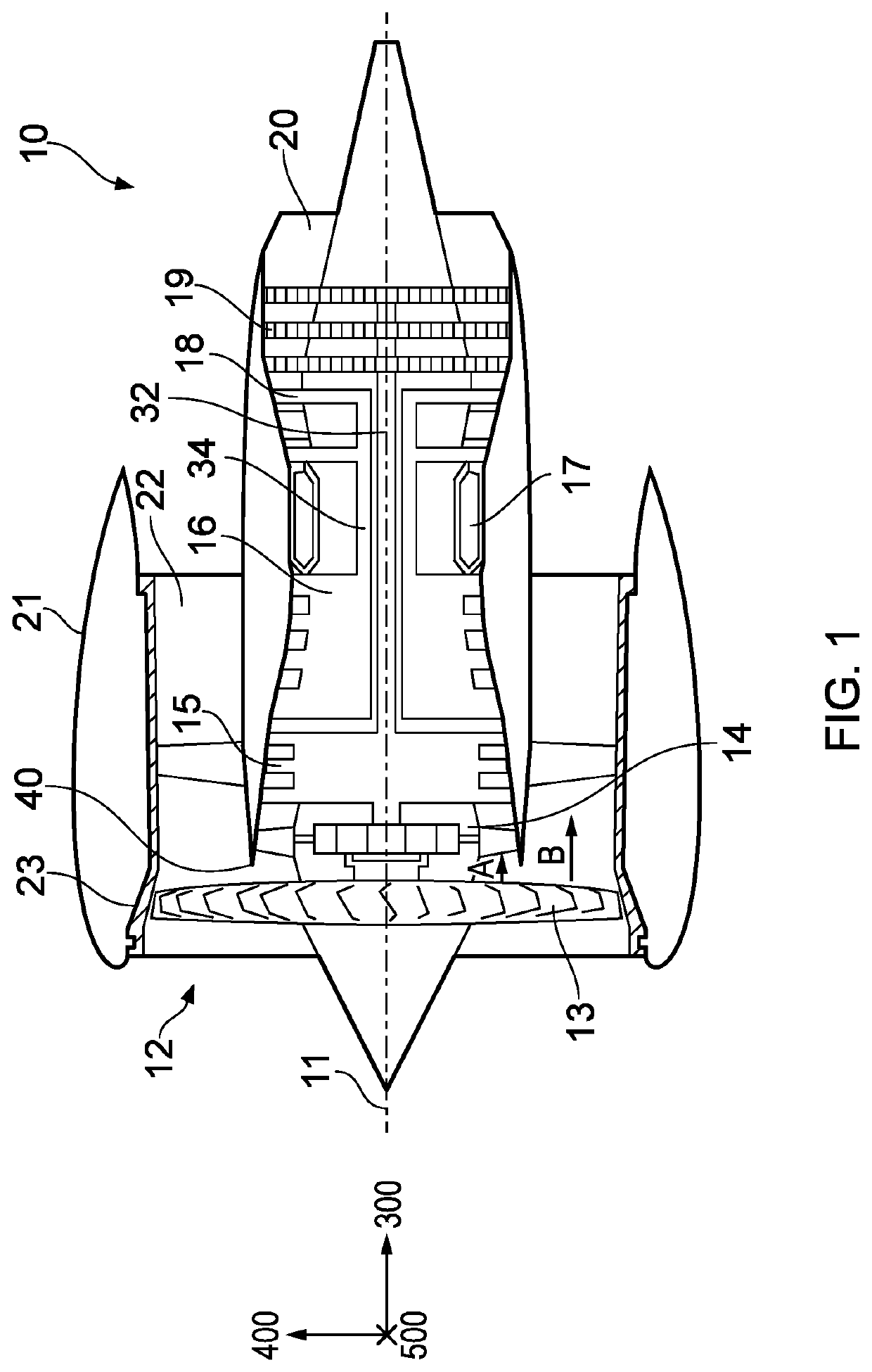
[0083]With reference to FIG. 1, a gas turbine engine is generally indicated at 10, having a principal and rotational axis 11. The engine 10 comprises, in axial flow series, an air intake 12, a propulsive fan 13, a gearbox 14, an intermediate pressure compressor 15, a high-pressure compressor 16, combustion equipment 17, a high-pressure turbine 18, a low-pressure turbine 19 and an exhaust nozzle 20. A nacelle 21 generally surrounds the engine 10 and defines the intake 12. The nacelle 21 may be, or may comprise, a fan containment case 23. The nacelle 21 and the fan case 23 may be separate components.

[0084]The gas turbine engine 10 works in the conventional manner so that air entering the intake 12 is accelerated and compressed by the fan 13 to produce two air flows: a first air flow A into the engine core and a second air flow B which passes through a bypass duct 22 to provide propulsive thrust. The first and second airflows A, B split at a generally annular splitter 40, for example a...


PUM


Abstract

A gas turbine engine 10 is provided in which a fan having fan blades 139 in which the camber distribution relative to covered passage of the fan 13 allows the gas turbine engine to operate with improved efficiency when compared with conventional engines, whilst retaining an acceptable flutter margin.

Description

CROSS-REFERENCE TO RELATED APPLICATIONS[0001]This specification is based upon and claims the benefit of priority from UK Patent Application Number 1719539.7 filed on 24 Nov. 2017, the entire contents of which are incorporated herein by reference.BACKGROUNDTechnical Field[0002]This disclosure relates to a gas turbine engine. Aspects of the disclosure relate to the camber distribution of the fan blades of a gas turbine engine.Description of the Related Art[0003]Modern gas turbine aero-engines typically comprise a fan, which compresses the incoming air and directs at least a portion of that air along a bypass duct, with the remainder of the air flowing through the engine core.[0004]It is desirable to optimize the overall efficiency of the engine, so as to minimize fuel burn (or specific fuel consumption). However, in designing the engine to have optimum efficiency, the present inventors have understood that other aspects of engine performance may be compromised. One such aspect may be ...

Claims


Application Information

Patent Timeline
Patent Type & Authority Patents(United States)
IPC IPC(8): F01D5/16F01D5/14F01D25/06
CPCF01D5/141F01D5/148F01D25/06F01D5/16F05D2240/301F05D2260/96F05D2220/323F05D2250/32F05D2220/36Y02T50/60
Inventor WILSON, MARK J.BARALON, STEPHANE M MPHELPS, BENEDICT
Owner ROLLS ROYCE PLC
Why Eureka
Try Eureka