Supercharge Your Innovation With Domain-Expert AI Agents!

Piezoelectric drive device

a drive device and piezoelectric technology, applied in the direction of piezoelectric/electrostrictive device details, instruments, device details, etc., can solve the problem of easy bending, and achieve the effect of effectively protecting the exposed end faces

Active Publication Date: 2021-01-19
TDK CORPARATION
View PDF12 Cites 0 Cited by
  • Summary
  • Abstract
  • Description
  • Claims
  • Application Information

AI Technical Summary

Benefits of technology

The piezoelectric drive device described in this patent prevents damage to the internal electrodes by using a laminated array of electrodes that can resist bending and cracking. Additionally, the device allows for the connection of an external circuit to either the weight member or the shaft, while effectively protecting the end faces of the device.

Problems solved by technology

Thus, there is a problem that it is easily bended when a load is applied to the shaft from a lateral direction.

Method used


Image

  • Piezoelectric drive device
  • Piezoelectric drive device
  • Piezoelectric drive device

Examples


first embodiment

The First Embodiment

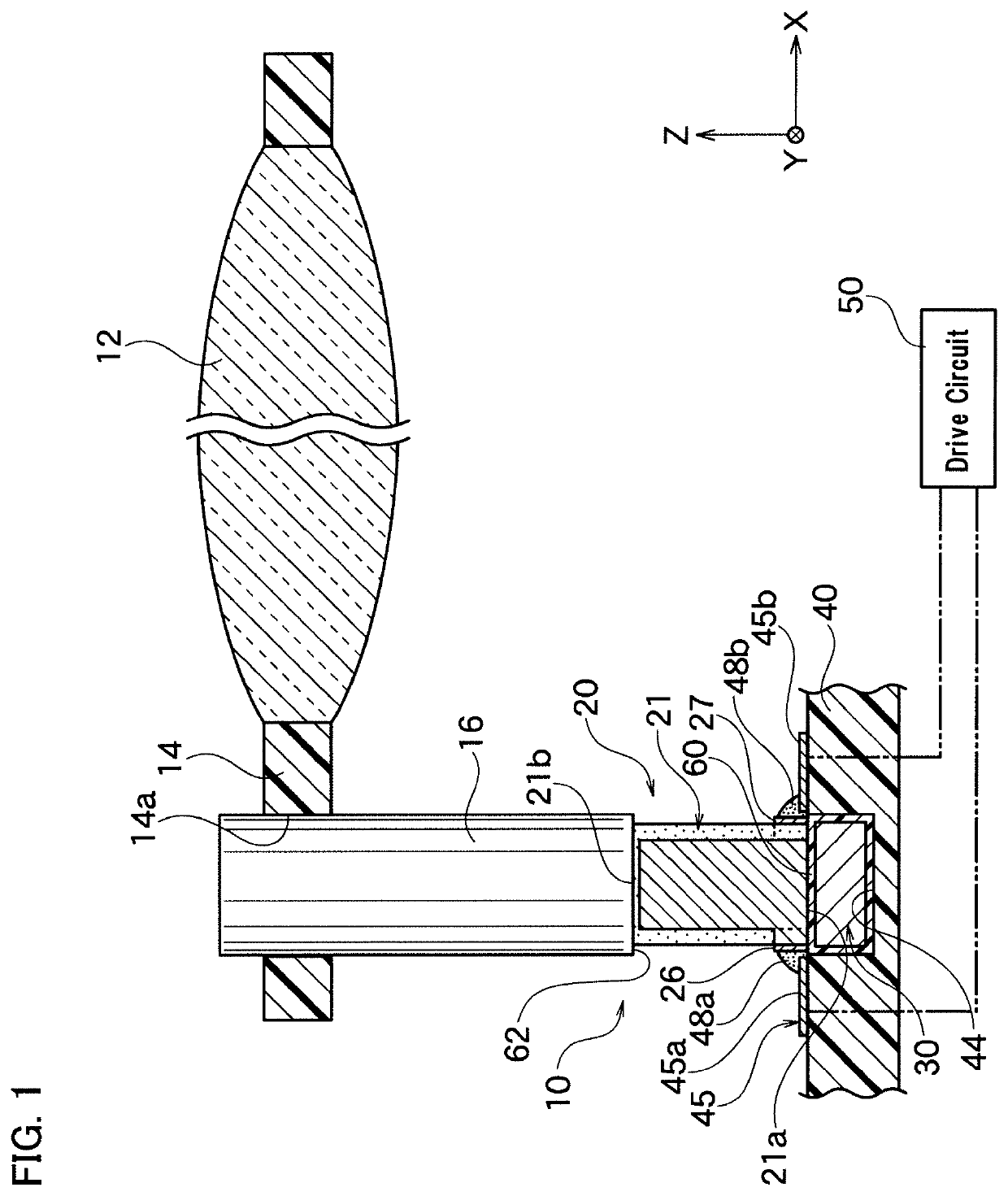
[0042]As shown in FIG. 1, piezoelectric drive device 10 according to an embodiment of the invention is a lens drive device, which moves lens frame 14, a movable body, holding lens 12 installed in such as a camera, along axial direction (Z axial direction) of shaft 16. Lens frame 14 is engaged to a predetermined position of shaft 16 in the axial direction by friction, and installed movably in the axial direction.

[0043]Shaft 16 vibrates by the laminated piezoelectric element 20 which stretches and vibrates in the axial direction. With said vibration, lens frame 14 is moved to one side or the other side of shaft 16 in Z axial direction. A moving direction and a moving amount are determined according to a formation of the voltage waveform or the applied time applied to laminated piezoelectric element 20.

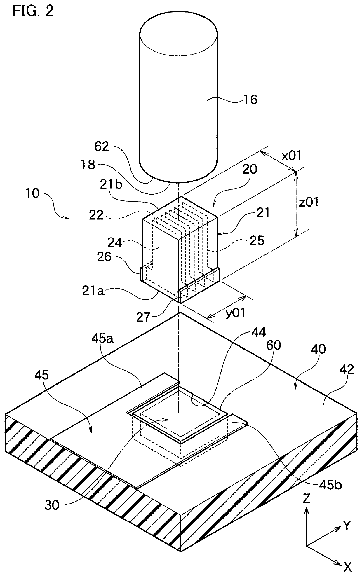
[0044]Piezoelectric drive device 10 includes shaft 16, laminated piezoelectric element 20 and weight member 30. Shaft 16 generally has a cylindrical form, and is comp...

second embodiment

The Second Embodiment

[0077]As shown in FIGS. 4A and 4B, laminated piezoelectric element 120 of the piezoelectric drive device according to the present embodiment has a similar composition with the same in the first embodiment and the similar effects can be obtained, except the patterns of the first internal electrode 124 and the same of the second internal electrode 125 are different from those in the first embodiment. Hereinafter, only the different part is mainly described in detail and an explanation of the common part is omitted. In addition, names of common parts are used for the common parts, and the overlapped explanation thereof is omitted.

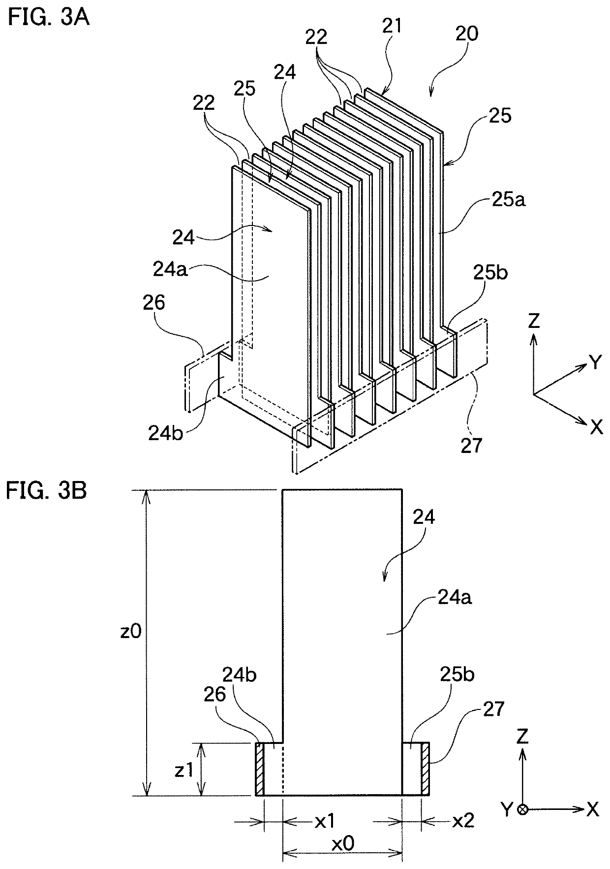
[0078]The first internal electrode 124 has electrode body 124a, having a width in X axial direction approximately the same with a width of element body 121 in X axial direction. Electrode body 124a forms cutout part 124b, at a side in X axial direction and at a bottom end in Z axial direction, in order to electrically insulate the second e...

third embodiment

The Third Embodiment

[0082]As shown in FIGS. 5A and 5B, laminated piezoelectric element 220 of the piezoelectric drive device according to the present embodiment has a similar composition with the same in the first embodiment and the similar effects can be obtained, except the patterns of the first internal electrode 224 and the same of the second internal electrode 225 are different from those in the first embodiment. Hereinafter, only the different part is mainly described in detail and an explanation of the common part is omitted. In addition, names of common parts are used for the common parts, and the overlapped explanation thereof is omitted.

[0083]The first internal electrode 224 has electrode body 224a, having a width in X axial direction narrower than a width of element body 221 in X axial direction. Electrode body 224a forms cutout part 224b, continuous in Z axial direction, at one side in X axial direction, in order to electrically insulate with the second external electrod...


PUM


Abstract

A piezoelectric drive device including: laminated piezoelectric element including a first end face and a second end face opposed to the first end face; a weight member attached to the first end face; and a shaft attached to the second end face, in which a moving member, engaged to the shaft movable in an axial direction, is moved by activating the laminated piezoelectric element. Inside the laminated piezoelectric element, a first internal electrode and a second internal electrode, respectively having a plane surface approximately perpendicular to the first end face and the second end face, are laminated in Y axial direction, approximately perpendicular to the first internal electrode and the second internal electrode with a piezoelectric layer in-between. The piezoelectric drive device, in which the laminated piezoelectric element is difficult to bend, even when the load is applied to the shaft from a lateral direction, is provided.

Description

BACKGROUND OF THE INVENTION1. Field of the Invention[0001]The present invention relates to a piezoelectric drive device moving a moving body, such as a lens frame, along a shaft.2. Description of the Related Art[0002]As the piezoelectric drive device, driving the lens frame in the axial direction using a laminated piezoelectric element, such as the device according to Patent Article 1 is known. As shown in Patent Article 1, according to the conventional piezoelectric drive device, a weight member is connected to a first end face of the laminated piezoelectric element and a shaft is connected to a second end face opposed to the first end face. Then, a vibration is applied to the shaft by driving the piezoelectric element, and the moving body is moved in the axial direction of the shaft.[0003]According to the laminated piezoelectric element used for the conventional piezoelectric drive device, generally an internal electrode and a piezoelectric layer are alternately laminated, to be p...

Claims


Application Information

Patent Timeline
Patent Type & Authority Patents(United States)
IPC IPC(8): H01L41/09H01L41/083B60J1/17E05F15/60G02B7/08H01L41/047H01L41/04H02N2/00H02N2/02H10N30/20H10N30/50H10N30/80H10N30/87H10N30/88
CPCH01L41/09H01L41/042H01L41/0471H01L41/0472H01L41/083H02N2/002H02N2/025B60J1/17E05F15/60G02B7/08H02N2/06H10N30/871H10N30/872H10N30/50H10N30/20H10N30/802
Inventor HOMMA, MITSUNAOHOSOKAWA, MASAHIRO
Owner TDK CORPARATION
Features
  • R&D
  • Intellectual Property
  • Life Sciences
  • Materials
  • Tech Scout
  • Unparalleled Data Quality
  • Higher Quality Content
  • 60% Fewer Hallucinations
Learn More