Ship with sail propulsion

a sail and propulsion technology, applied in the field of sail propulsion, can solve the problems of difficult, fragile, and even impossible implementation of droppable or reefable airfoils, and achieve the effect of large aerodynamic efficiency and great simplicity of us

Active Publication Date: 2021-02-02
VISTAHOLM P O BOX54 S 523 01 ULRICEHAMN SWEDEN
View PDF36 Cites 3 Cited by
  • Summary
  • Abstract
  • Description
  • Claims
  • Application Information

AI Technical Summary

Benefits of technology

[0008]The aim of the present invention is to propose an airfoil with at least two flaps which remedies all or part of the disadvantages and limitations mentioned above and which provides a large aerodynamic efficiency and great simplicity of use.

Problems solved by technology

However, these known airfoils have significant problems when it comes to making a droppable sail and further do not allow reefing.
Also, the relative movement of the second flap relative to the first flap is in general achieved by rotation from an axis located inside the profile of the first flap, which is not optimal from the performance perspective and makes the implementation of a droppable or reefable airfoil delicate or even impossible.

Method used


Image

  • Ship with sail propulsion
  • Ship with sail propulsion
  • Ship with sail propulsion

Examples


first embodiment

[0058]First, with reference to FIGS. 1 to 11, the invention is going to be described.

[0059]a) General Principles

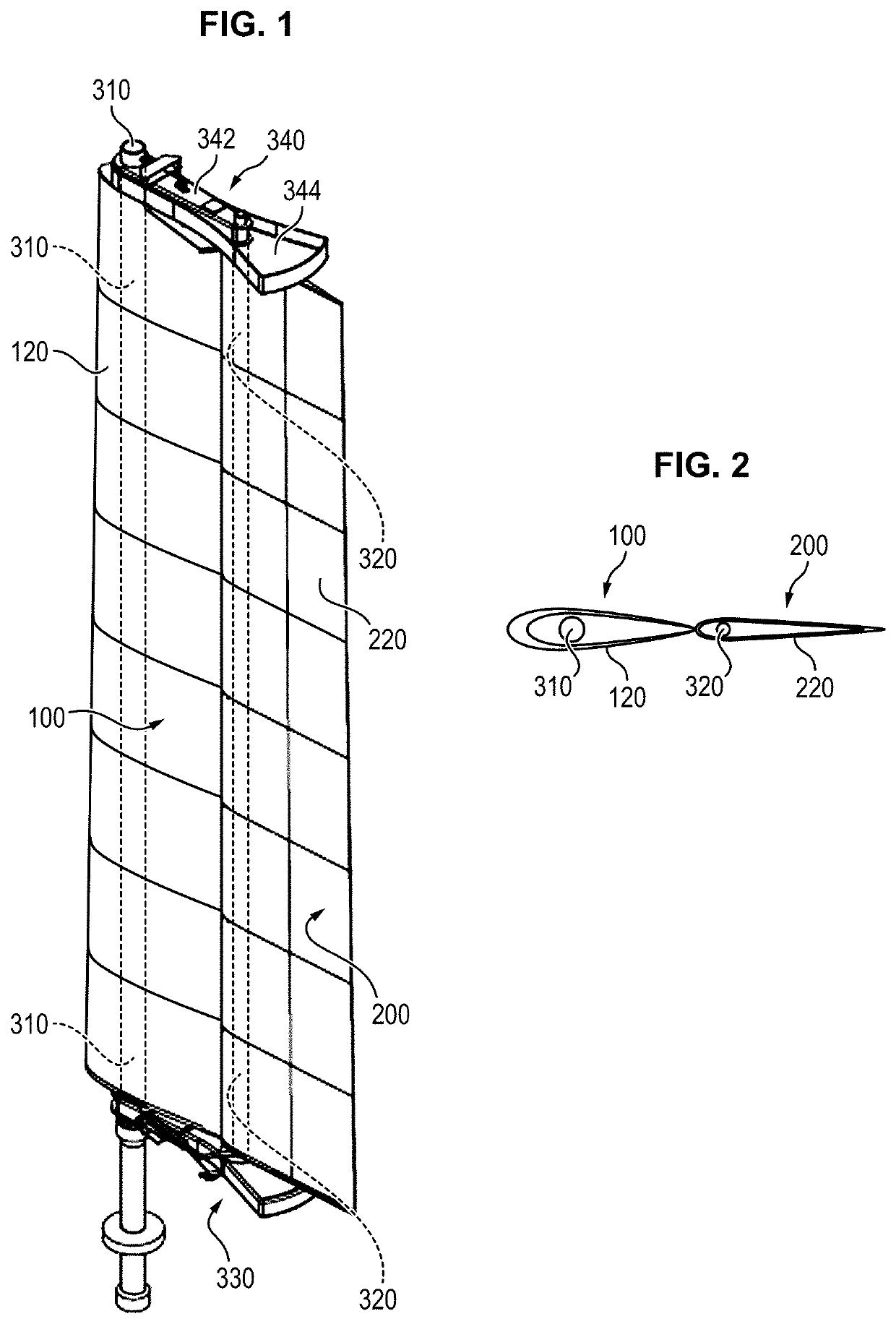
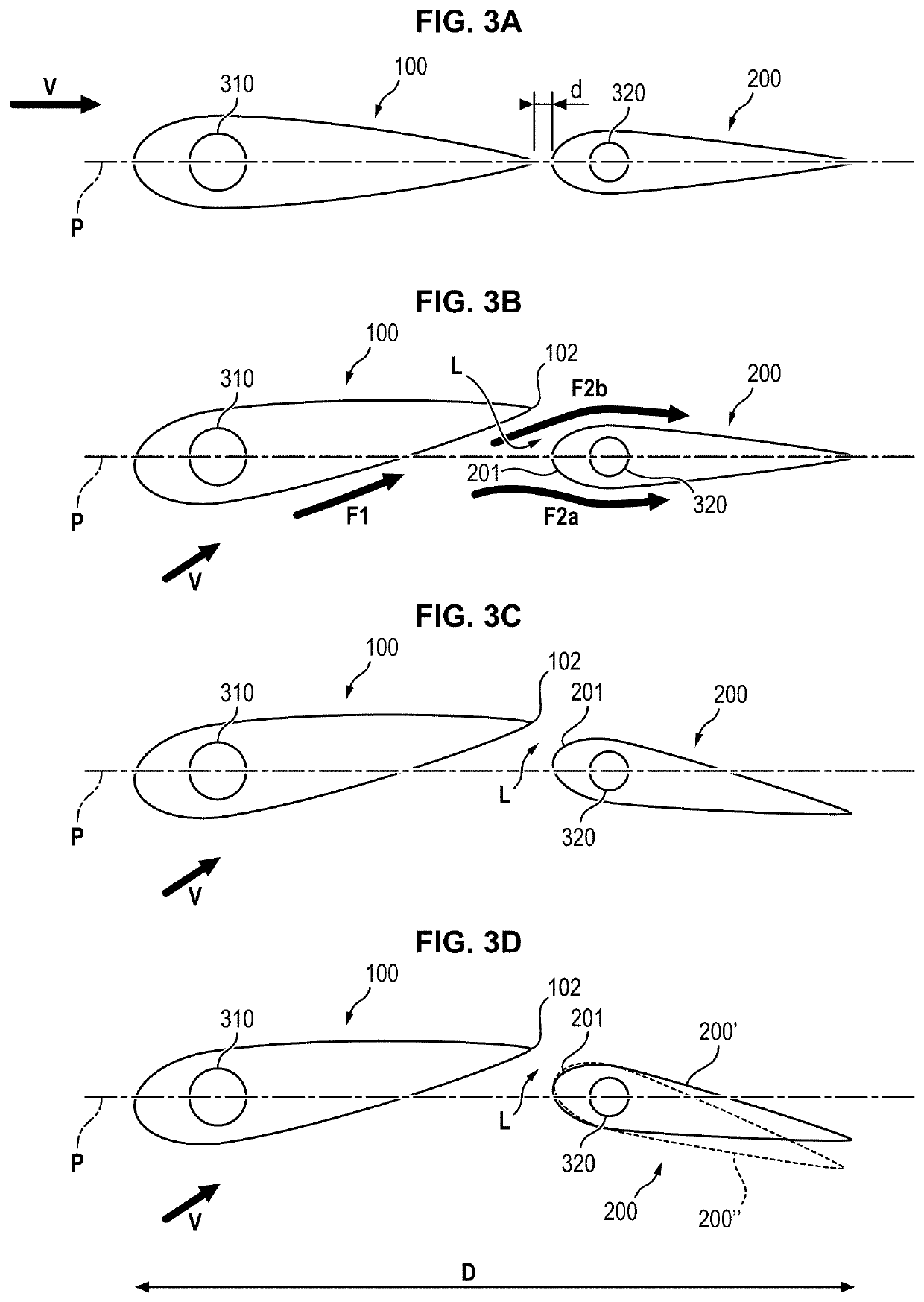
[0060]With reference to FIGS. 1, 2 and 3A to 3D, an airfoil according to this embodiment comprises two aerodynamic profiles both adjustable in incidence and for which the relative camber angle is adjustable. In the following, they are called first flap or fore flap, and second flap or aft flap. They are designated by the references 100 and 200 respectively. They pivot on the axes defined by two masts 310, 320 as is going to be seen in the following.

[0061]At least one of these profiles has an asymmetric aerodynamic transverse section in the fore-to-aft direction (with leading edge and trailing edge). It can for example involve sections called symmetric aircraft airfoil, and more preferably NACA 00xx standardized sections or others.

[0062]The relative angle of the second flap relative to the first flap is differentially adjustable along the height thus allowing a washout of t...

second embodiment

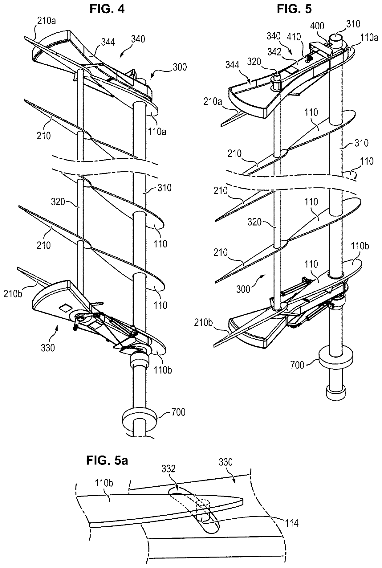
[0108]In a second embodiment, the command can be made at a distance from the mast by using a transmission such as a pulley 700 (possibly notched) secured to the mast 310 in the lower region thereof (see FIGS. 4 and 5) and connected to a control mechanism (manual, electrical, hydraulic, etc.) via a belt, a gearing, etc. In a particular embodiment, as shown in FIG. 24, the device for rotating mast 310 comprised a gearmotor 710 engaging a toothed wheel 720 coaxial with the mast.

[0109]Finally, in particular for light sector board type craft or small pleasure boats, a sheet and tackle can be simply provided analogously to the control of a traditional mainsail. The lashing is then done in the area of the aft region of the boom member 330.

[0110]In every case, to be sure that the rigid frame made up of the two masts 310, 320, the boom member 330 and the fixed member 342 of the gaff 340 turns as a whole during this angular adjustment, the members 330, 342 are mounted on the fore mast 310 so ...


PUM


Abstract

The invention relates to an at least partially wind-propelled ship, comprising a double airfoil mounted on a structure controlled angularly around a generally vertical axis, where the double airfoil comprises a fore flap and an aft flap separated by a slit. At least one of the fore flap and the aft flap has a fore-to-aft asymmetry, wherein each flap comprises a series of shape members distributed in height. The structure comprises a fore mast and an aft mast connected by a boom member and by a gaff member. The shape members of the fore flap are traversed by the fore mast while being able to turn around an axis defined thereby, while the shape members of the aft flap are traversed by the aft mast while being able to turn around an axis defined thereby.

Description

FIELD OF THE INVENTION[0001]The present invention relates generally to sail propulsion, and more specifically to a new type of propulsion airfoil for cruise boats and working ships.STATE OF THE ART[0002]The prior literature relating to rigid airfoils for propulsion of natives is abundant.[0003]Thus, in particular rigid or semi-rigid airfoils with two flaps, with which in particular to give the airfoil an adjustable camber are known from documents U.S. Pat. Nos. 3,332,383 A, 4,685,410 A, 5,313,905 A and 8,635,966 B1.[0004]However, these known airfoils have significant problems when it comes to making a droppable sail and further do not allow reefing. Thus existing airfoils with two flaps most often have a shrouded mast and control of the airfoil is done by means of lanyards which constitute both a sheet which forces the airfoil camber and also a fixed linkage which drives the second flap so as to make it reach all or part of the camber at the base of the wing, so as to generate a was...

Claims


Application Information

Patent Timeline
Patent Type & Authority Patents(United States)
IPC IPC(8): B63H9/061
CPCB63H9/061B63H9/1021B63H9/0635B63B2035/009Y02T70/5236
Inventor VAN PETEGHEM, MARCSDEZ, NICOLAS
Owner VISTAHOLM P O BOX54 S 523 01 ULRICEHAMN SWEDEN
Why Eureka
Try Eureka