
Method and device for estimating battery life

a battery life and lifetime estimation technology, applied in secondary cells, electrochemical generators, instruments, etc., can solve the problems of inability to apply real-time lifetime estimation, different lifetime in use, and difficulty in accurately measuring capacity, so as to accurately estimate the remaining lifetime of the battery in use and emphasize product reliability.

Active Publication Date: 2021-02-02
HYOSUNG HEAVY IND CORP
View PDF19 Cites 0 Cited by
  • Summary
  • Abstract
  • Description
  • Claims
  • Application Information

AI Technical Summary

Benefits of technology

[0020]There is an advantage in that the battery lifetime estimating method or apparatus according to the above-described configuration can more accurately estimate the remaining lifetime of a battery in use.
[0021]In terms of ESS providers and operators, the battery lifetime estimating method or apparatus according to the present invention has the advantage that maintenance and use periods can be checked on the basis of the accurate remaining lifetime of the constructed ESS.
[0022]In terms of the ESS manufacturer, the battery lifetime estimating method or apparatus according to the present invention has an advantage that it is possible to emphasize product reliability and technical advantage by predicting an overall lifetime and a remaining lifetime of the manufactured product.

Problems solved by technology

However, this has a problem in that it is impossible to perform the measurement at a site using partially charging / discharging, and it is difficult to accurately measure the capacity even at a site where fully charging / discharging is mainly performed, so that this cannot be applied to real-time lifetime estimation.
In addition, in the case of a battery device configured with battery cells of the same kind and the same combination, the lifetime in use is different due to the environment in which the battery is used and the deviation of the battery cells, and there is not method of accurately estimating the remaining lifetime of each battery.

Method used


Image

  • Method and device for estimating battery life
  • Method and device for estimating battery life
  • Method and device for estimating battery life

Examples


Embodiment Construction

[0030]Hereinafter, embodiments of the present invention will be described with reference to the accompanying drawings.

[0031]In describing the present invention, the terms “first”, “second”, and the like may be used to describe various components, but the components may not be limited by the terms.

Terms are used only for the purpose of distinguishing one component from the others.

For example, the first component may be referred to as a second component without departing from the scope of the present invention, and similarly, the second component may also be referred to as a first component.

[0032]In the case where a certain component is referred to as being connected or coupled with another component, the certain component may be directly connected to or coupled with another component, but it can be understood that still another component may be present therebetween.

[0033]The terms used in this specification are used only for the purpose of describing particular embodiments, but the t...


PUM

PropertyMeasurementUnit
charging voltageaaaaaaaaaa
battery capacityaaaaaaaaaa
lifetime estimatingaaaaaaaaaa

Abstract

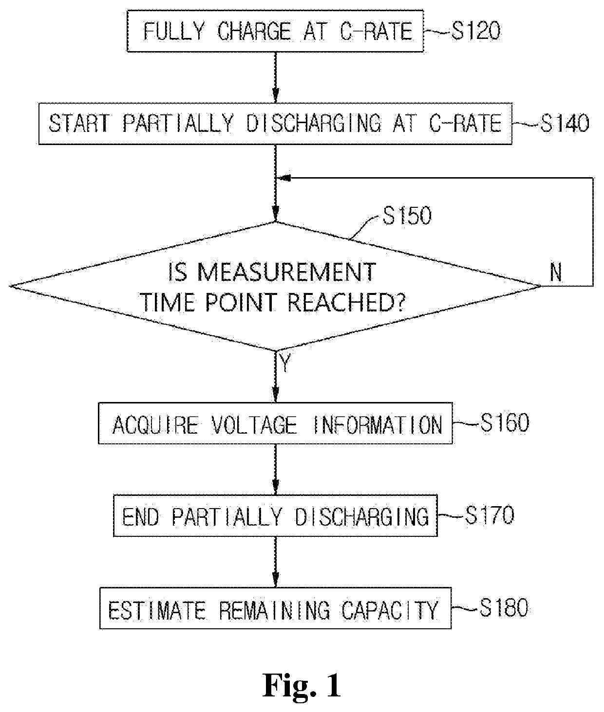
Provided is a battery lifetime estimating method including steps of: fully charging a battery according to a predetermined charging condition; partially discharging the fully charged battery according to a predetermined discharging condition; acquiring voltage information at a plurality of predetermined measurement time points while performing the partially discharging; and estimating a remaining capacity of the battery by using the acquired voltage information. Herein, the step of estimating the remaining capacity of the battery includes steps of: calculating the capacity of the battery in one cycle of fully charging / discharging in which the measurement is performed from the measured voltage drop amounts; and estimating the remaining lifetime of the battery by applying a statistical technique to the capacity of the battery calculated with respect to a plurality of cycles of fully charging / discharging.

Description

TECHNICAL FIELD[0001]The present invention relates to a battery lifetime estimating method or apparatus, and more particularly, to a battery lifetime estimating method or apparatus capable of accurately estimating the remaining lifetime of a battery in use during actual use of the battery by applying a statistical technique.BACKGROUND ART[0002]Domestically and internationally, studies on rechargeable batteries (hereinafter, referred to as “rechargeable batteries” or “batteries”) are increasing significantly in association with electric vehicles and ESS (Energy Storage System).The studies on the rechargeable batteries are generally focused on increasing the capacity of the rechargeable battery, reducing the weight of the rechargeable battery, and improving performance such as rapid charging of the rechargeable battery.[0003]The importance of predicting failure of rechargeable battery was recognized due to accidents caused by the unexpected failure of a rechargeable battery such as th...

Claims


Application Information

Patent Timeline
Patent Type & Authority Patents(United States)
IPC IPC(8): H02J7/00H02J7/14G01R31/392H01M10/42H01M10/48G01R31/3835H01M10/44H01M10/0525
CPCG01R31/392G01R31/3835H01M10/42H01M10/446H01M10/448H01M10/48H01M10/0525G01R31/367Y02E60/10
Inventor PARK, SANG HUISONG, HWA SEOBKIM, JI SUNGCHOI, JOO HOLEE, JAE WOOK
Owner HYOSUNG HEAVY IND CORP
Learn More