Turbocharger device

a turbocharger and device technology, applied in the direction of electric control, combustion engines, machines/engines, etc., can solve the problems of high cost, high material strength, high durability, etc., and achieve the effect of reducing the initial cost of the turbocharger, facilitating the acquisition of operational history information, and accurately predicting the life of the turbocharger

Active Publication Date: 2018-06-26
MITSUBISHI HEAVY IND LTD
View PDF105 Cites 0 Cited by
  • Summary
  • Abstract
  • Description
  • Claims
  • Application Information

AI Technical Summary

Benefits of technology

[0032]According to the present invention, it is possible to predict a lifetime of a turbocharger accurately, and if the lifetime expires, the turbocharger can be replaced along with a turbo controller (turbo ECU) having recorded data of the operational history of the turbocharger, which makes it possible to facilitate acquisition of the operational history information of the turbocharger and reduce the initial costs of the turbocharger.

Problems solved by technology

However, an operation history (e.g. operation time, rotation speed, and cumulative damage level) of a turbocharger is not sufficiently understood.
Further, a turbocharger is required to have a high reliability, and thus to be designed with sufficient safety, which results in having a high spec in terms of material strength (high strength, high durability) and a high cost.

Method used


Image

  • Turbocharger device
  • Turbocharger device
  • Turbocharger device

Examples


first embodiment

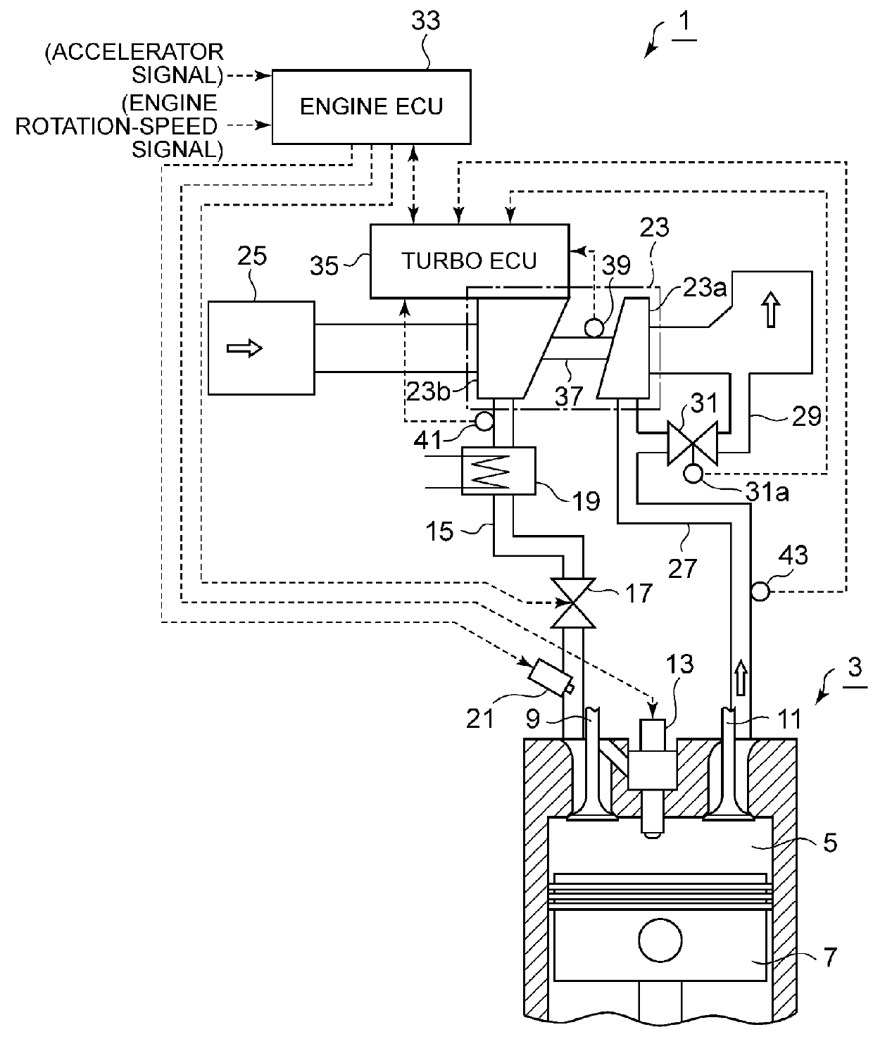
[0049]FIG. 1 illustrates an overall configuration of a turbocharger device 1 according to the first embodiment of the present invention. The engine 3 is a diesel engine or a gasoline engine to be mounted to a vehicle, a truck, a bus, a ship, an industrial engine, or the like. A gasoline engine is illustrated in the present example, the gasoline engine including a combustion chamber 5, a piston 7, an intake valve 9, an exhaust valve 11, and an ignition plug 13. A throttle valve 17 and an inter cooler 19 are disposed in an intake channel 15, and a fuel injection nozzle 21 is disposed on an intake port at a downstream side of the throttle valve 17 with respect to a flow of intake air.

[0050]Further, the engine 3 includes an exhaust turbocharger (turbocharger) 23, the turbocharger 23 including a turbine 23a rotated by exhaust gas from the engine 3 and a compressor 23b driven to rotate by the turbine 23a to supercharge intake air to the engine 3. Air flows into the compressor 23b via an a...

second embodiment

[0071]Next, with reference to FIG. 9, the second embodiment of the lifetime estimation unit 49 of the turbo ECU 35 will now be described.

[0072]First, in step S31, the lifetime estimation unit 53 of the second embodiment calculates a surge margin on the basis of the average boost pressure or the maximum boost pressure in the period between the regular intervals. A turbocharger deteriorates in performance with the operating time, and an actual allowance (surge margin) of a supply-air pressure with respect to a surge pressure at which surging occurs determined on the basis of the performance characteristics of an unused compressor decreases as compared to that in an unused state.

[0073]Thus, the surge margin is calculated and the lifetime is determined using the value of the surge margin as an index. Specifically, the surge margin is calculated as a difference between the surge pressure and the actual boost pressure with respect to the actual boost pressure.

[0074]Next, in step S32, the ...

third embodiment

[0085]Next, with reference to FIGS. 10 to 13, the third embodiment of the lifetime estimation unit 49 of the turbo ECU 35 will be described.

[0086]In the third embodiment, the determination of the lifetime estimation unit 54 is not based on the boost pressure, the rotation speed, the exhaust temperature, or the like in a period between regular intervals, unlike the first and second embodiments, but on information on occurrence number of an extreme value of the rotation-speed fluctuation of the turbocharger 23 and the corresponding rotation speed, the information being recorded throughout the entire operating period.

[0087]As illustrated in FIG. 10, the lifetime estimation unit 54 includes a rotation-speed extreme-value determination part 55 which determines the extreme value of the rotation speed, a stress calculation part 56 which calculates a stress amplitude from the rotation speed of the rotation-speed extreme value, a repetition-number calculation part 57 which calculates a repet...


PUM


Abstract

A turbocharger device includes: a turbocharger (3); and a turbo controller (35) configured to control a waste-gate valve (31) or a variable-displacement mechanism of an exhaust-gas amount supplied to the turbine to control a boost pressure of the turbocharger, the turbo controller (35) including a control calculation part (44) and a sensor signal input part (45) provided separately and independently from an engine controller (33) and being mounted to a compressor housing at a side of the compressor (23b) of the turbocharger (3).

Description

TECHNICAL FIELD[0001]The present invention relates to a turbocharger device for an engine, especially to an arrangement of a control device for controlling a turbocharger and lifetime estimation of the turbocharger performed by the control device.BACKGROUND ART[0002]In an engine used for an automobile or the like, an exhaust turbocharger is widely used, in which a turbine is rotated by exhaust gas energy of the engine and a centrifugal compressor directly coupled to the turbine via a rotation shaft compresses intake air and supplies the engine with the intake air, to improve the output of the engine.[0003]Such an exhaust turbocharger is required to have a lifetime of hundreds of thousands kilometers for automobiles, equivalent to that of the automobiles, or a lifetime of more than a million kilometers for trucks and buses.[0004]However, an operation history (e.g. operation time, rotation speed, and cumulative damage level) of a turbocharger is not sufficiently understood. Further, a...

Claims


Application Information

Patent Timeline
Patent Type & Authority Patents(United States)
IPC IPC(8): F02D23/00F02D41/00F02D41/22F02D41/14F02B37/24F02B37/18F02B39/16F02B37/12
CPCF02B37/18F02B37/24F02B39/16F02D41/0007F02D41/1446F02D41/22Y02T10/40F02B2037/125F02B2039/166F02B2039/168Y02T10/144Y02T10/16Y02T10/12
Inventor MATSUO, ATSUSHIYOKOYAMA, TAKAO
Owner MITSUBISHI HEAVY IND LTD
Why Eureka
Try Eureka